
SLIDE 1
The CG Camera
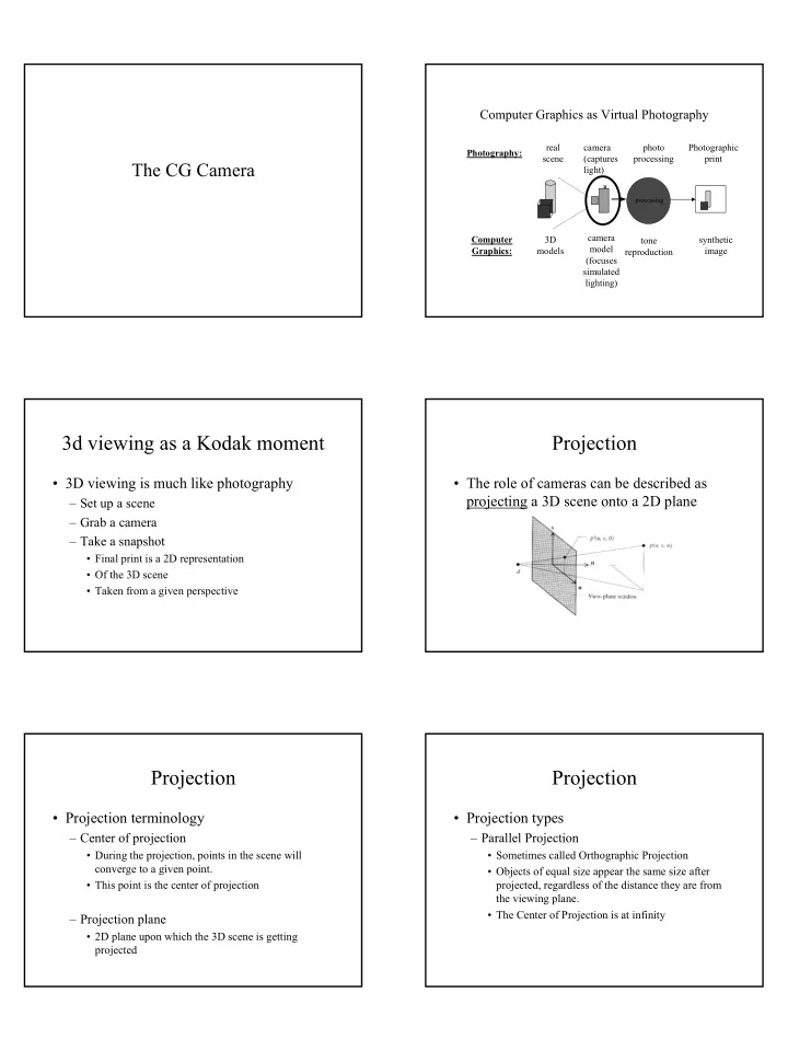
Computer Graphics as Virtual Photography
camera (captures light) synthetic image camera model (focuses simulated lighting)
processing
photo processing tone reproduction real scene 3D models Photography: Computer Graphics: Photographic print
3d viewing as a Kodak moment
- 3D viewing is much like photography
– Set up a scene – Grab a camera – Take a snapshot
- Final print is a 2D representation
- Of the 3D scene
- Taken from a given perspective
Projection
- The role of cameras can be described as
projecting a 3D scene onto a 2D plane
Projection
- Projection terminology
– Center of projection
- During the projection, points in the scene will
converge to a given point.
- This point is the center of projection
– Projection plane
- 2D plane upon which the 3D scene is getting
projected
Projection
- Projection types
– Parallel Projection
- Sometimes called Orthographic Projection
- Objects of equal size appear the same size after
projected, regardless of the distance they are from the viewing plane.
- The Center of Projection is at infinity