SLIDE 1
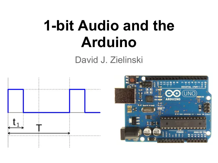
1-bit Audio and the Arduino
David J. Zielinski
SLIDE 2 Overview
- 1. Terminology of Sound
- 2. Atari 2600
- a. clock division frequencies
- b. linear feedback shift registers
- 3. Arduino Uno
- a. Specifications
- b. Audio Generation Methods
- c. Code Examples and Demos
- d. Arduino Due
- e. Future Work
SLIDE 3 sound waves are oscillations in air
- pressure. The amplitude (viewed on y axis)
is proportional to the change in pressure 1 = Peak amplitude 2 = Peak-to-peak amp 3 = RMS amplitude 4 = Wave period
SLIDE 4
loudness is the perceptual sense of amplitude. quiet vs loud frequency is the number of repeating events per unit time. pitch is the perceptual sense of frequency.
SLIDE 5
bit depth is seen as quantization on the y axis
SLIDE 6
Retail availability 1977 Introductory price 199 USD Units sold 30 million CPU MOS 6507 @ 1.19 MHz Memory 128 bytes RAM, 4 kB ROM
Atari 2600
SLIDE 7
- MOS 6532 (RIOT) Ram-I/O-Timer
- MOS 6507. Smaller/Cheaper version of the 6502
(used in Apple, Atari, Commodore)
- Television Interface Adaptor (TIA)
SLIDE 8 Atari TIA Chip
- non-frame buffer design!
- reading input controllers
- sound effects
○ 2 independent noise generators ○ 5-bit frequency divider ○ 4-bit audio control (sets waveform) ○ 4-bit volume control
Jay Glenn Miner (May 31, 1932 – June 20, 1994) was a famous American integrated circuit designer, known primarily for his work in multimedia chips and as the "father of the Amiga". Lead developer of the TIA chip.
SLIDE 9
SLIDE 10 String/Tube Resonance Pitch Perception
100 hz - root 200 hz - octave 300 hz - 5th 400 hz - octave 500 hz - Major 3rd 600 hz - minor 3rd
2 2 5th: 300/200 3/2 1.5 4th: 400/300 4/3 1.33_ Maj3: 500/400 5/4 1.25 min3: 600/500 6/5 1.2 6th: 500/300 5/3 1.66_
SLIDE 11 C C# D D# E F F# G G# A A# B C blue = equal temperament red = just intonation pitch freq ratio
SLIDE 12
- ne reason classic video games
sound distinctive is the utilization of the clock division technique which results in a scale based on the undertone series.
SLIDE 13 blue = just intonation red = harmonic undertone cents Pitch
SLIDE 14 Gioseffo Zarlino (1517-1590) was an Italian music theorist and composer of the Renaissance.
First proposed the idea of the undertone series.
Hermann Ludwig Ferdinand von Helmholtz (1821 – 1894) was a German physician and physicist who made significant contributions to several widely varied areas of modern science.
Argued that sympathetic resonance is at least as active in under partials as in
SLIDE 15
Harmonic Undertone Demo
http://jackaudio.org/
SLIDE 16
4 bit poly, 5 bit poly, 9 bit poly
SLIDE 17
XOR (exclusive or)
A B Output 1 1 1 1 1 1
SLIDE 18 Linear Feedback Shift Register
Poly4: Taps at 2 and 3
1 0 0 1
Now
1 1 0 0
Future
SLIDE 19
Demo of LFSR Poly4: taps at 2,3 Poly5: taps at 2,4 Poly9: taps at 4,8
SLIDE 20
Arduino Uno
Flash / Program Memory 32 KB SRAM / Variable Memory 2 KB Clock Speed 16 MHz 5v $30
SLIDE 21 Why arduino?
- low cost. leave installed for installation.
- input: knobs, switches, pressure sensors,
accelerometers, ultrasonic distance, temperature, capacitive sensing.
- output: usb, control motors, lights, and audio
- making things is more fun then buying things
- open source hardware/software
- manufactured in Italy
- subset of C++
SLIDE 22
Where can you get it (and components)?
In Person: Radio Shack [northgate mall] Hobbyist: sparkfun.com adafruit.com Pro: digikey.com newark.com
SLIDE 23 Methods of Running
- With a computer. Use arduino to read input,
then send via serial message (via USB cable) to computer for further action.
- Stand alone. Arduino reads input and does
any processing on board.
SLIDE 24 Methods to Generate Audio
Type Pro Con tone function call
- part of standard libraries.
- pitch is accurate.
- monophonic (1 pitch at a
time).
add on shield
- actual audio output (24bit, 44k).
- arduino uno processor is
too slow.
pin toggle in main loop
- generate arbitrary 1-bit waveforms.
- polyphonic (multiple pitches).
- simple programming
- 1-bit waveforms
- pitch not accurate
- highest pitch limited by
amount of processing pin toggle in interrupt
- generate arbitrary 1-bit waveforms.
- polyphonic (multiple pitches).
- pitch is accurate
- 1-bit waveforms
- complicated programming
- need buffer = latency
SLIDE 25
Things you will need:
SLIDE 26
How does electricity work?
SLIDE 27
How to convert 5v to 0.45v ? Solution: voltage divider
SLIDE 28
What does this look like?
SLIDE 29
Pitch Linear
void loop() { int v = analogRead(A0); int v_half=v/2; if(current_sample<v_half) digitalWrite(2,HIGH); else digitalWrite(2,LOW); current_sample=(current_sample+1)%v; }
SLIDE 30
Pitch Exp
void loop() { int v = analogRead(A0); int vp=int(pow(v,2.0)/5000.0); int v_half=vp/2; if(current_sample<v_half) digitalWrite(2,HIGH); else digitalWrite(2,LOW); current_sample=(current_sample+1)%vp; }
SLIDE 31 samples input value
SLIDE 32
Noise
void loop() { int v = analogRead(A0); int vp=int(pow(v,2.0)/5000.0); if(current_sample==0) { int val=random(2); if(val==1) digitalWrite(2,HIGH); else digitalWrite(2,LOW); } current_sample=(current_sample+1)%vp; }
SLIDE 33
Dual Pitch
void loop() { int v = analogRead(A0); int v2 = analogRead(A1); s1.set_freq(v); s1.tick(); s2.set_freq(v2); s2.tick(); }
SLIDE 34
AND aka Ring Mod
void loop(){ int v = analogRead(A0); int v2 = analogRead(A1); s1.set_freq(v); s2.set_freq(v2); int d=s1.get_val(); int d2=s2.get_val(); byte f=d&d2; digitalWrite(2,f); }
A B Output 1 1 1 1 1
SLIDE 35
XOR aka Korg MS-20 Ring Mod
void loop(){ int v = analogRead(A0); int v2 = analogRead(A1); s1.set_freq(v); s2.set_freq(v2); int d=s1.get_val(); int d2=s2.get_val(); byte f=d^d2; digitalWrite(2,f); }
A B Output 1 1 1 1 1 1
SLIDE 36
byte val=pgm_read_byte_near(pos); if(val>128) digitalWrite(2,HIGH); else digitalWrite(2,LOW); pos++; if(pos>pos_end) pos=start_pos;
Program Material
SLIDE 37
Decimation Delay
byte val=delay_array[d_pos]; int prob=random(0,1024); dv=(val>0 && prob<decay) || pbyte; delay_array[d_pos]=dv; d_pos=(d_pos+1)%dtime; digitalWrite(3,val); digitalWrite(2,pbyte);
SLIDE 38
Looper
if (sensorVal>0) {
pbyte=pitch_sample<phalf; triggered=true; } pitch_sample=(pitch_sample+1)%pmax; byte val=delay_array[d_pos]; if(triggered) delay_array[d_pos]=pbyte; else delay_array[d_pos]=val; d_pos=(d_pos+1)%dtime; digitalWrite(2,pbyte); digitalWrite(3,val);
SLIDE 39
Arpeggiation
byte notes[6]={1,2,4,8,4,2}; int vpn=sensor_val*notes[current_note]; int v_half=vpn/2; digitalWrite(2,current_sample<v_half); current_sample=(current_sample+1)%vpn; note_sample++; if(note_sample>samples_per_note){ note_sample=0; current_note=(current_note+1)%6; }
SLIDE 40 Arduino Due
Due Uno Clock Speed 84 Mhz 16 Mhz SRAM (Variables) 96 KB 2 KB Flash (Program) 512 KB 32 KB Voltage 3.3v 5v Analog Input 12 [12 bit] 6 [10 bit] Analog Output (D/A) 2 Digital Pins 54 14 Price $50 $30
SLIDE 41
Guitar Effect Pedal
SLIDE 42
Active Paintings
SLIDE 43
Skull Drum and Leg- Tar
SLIDE 44
P10 Project 100, 1k, 10k, ... channel installation
SLIDE 45
Thank You!
SLIDE 46
Wet Ink Ensemble @ Casbah 8pm featuring Kenneth Stewart's "Make It Opaque"
SLIDE 47