
SLIDE 1
Laboratory for Perceptual Robotics – Department of Computer Science
Embedded Systems Intro to the Arduino
2 Laboratory for Perceptual Robotics – Department of Computer Science
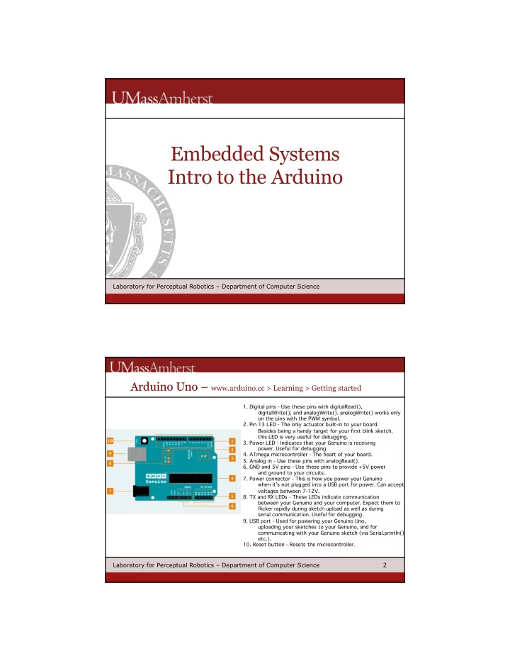
Arduino Uno – www.arduino.cc > Learning > Getting started
- 1. Digital pins - Use these pins with digitalRead(),
digitalWrite(), and analogWrite(). analogWrite() works only
- n the pins with the PWM symbol.
- 2. Pin 13 LED - The only actuator built-in to your board.
Besides being a handy target for your first blink sketch, this LED is very useful for debugging.
- 3. Power LED - Indicates that your Genuino is receiving
- power. Useful for debugging.
- 4. ATmega microcontroller - The heart of your board.
- 5. Analog in - Use these pins with analogRead().
- 6. GND and 5V pins - Use these pins to provide +5V power
and ground to your circuits.
- 7. Power connector - This is how you power your Genuino
when it’s not plugged into a USB port for power. Can accept voltages between 7-12V.
- 8. TX and RX LEDs - These LEDs indicate communication
between your Genuino and your computer. Expect them to flicker rapidly during sketch upload as well as during serial communication. Useful for debugging.
- 9. USB port - Used for powering your Genuino Uno,
uploading your sketches to your Genuino, and for communicating with your Genuino sketch (via Serial.println() etc.).
- 10. Reset button - Resets the microcontroller.