Wire Crossing Patterns Maxim Potekhin (BNL) Wirecell Summit@LBNL - - PowerPoint PPT Presentation
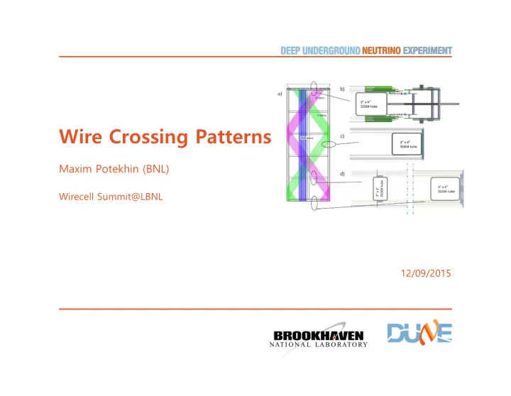
Wire Crossing Patterns Maxim Potekhin (BNL) Wirecell Summit@LBNL 12/09/2015 Nominal pattern according to the CDR Parameters from the CDR: The scale of the pitch seems about right based on diffusion etc but the exact choice of numbers is
M Potekhin | Wire Patterns 20151209
Nominal pattern according to the CDR
- Parameters from the CDR:
- The scale of the pitch seems about right based on diffusion etc but the
exact choice of numbers is not documented in the CDR.
- How well is it justified by the physics requirements?
–
- cf. Milind's talk regarding the "requirements cascade" in Milind's talk, science objectives
should not be compromised.
- Does this table contain rounded numbers? (Answer is yes). See next slide.
2
M Potekhin | Wire Patterns 20151209
CDR pitch visualized
- Obviously, no nice pattern like in μBooNE
- At first glance, there is 6 wire "beat pattern",
which has at least some periodicity, but...
– Induction plane intersections with the horizontal axis, period: 5.75063998388700648... – Collection plane intersections, period: 4.79
– Their ratio: 1.200551144861587...
- Since this issue was discussed last time in
October, it was confirmed that the numbers have been rounded off...With nominal pitch creeping misalignment will amount to 0.53mm across the width of the APA
- There are "more precise numbers" so the
ratio will be precisely 6/5 (good!)
- According to engineers, wire positioning will
be a challenge, but it's likely be met
- Currently main motivation for choice of pitch
is the size of electronics board relative to
- ther elements of the detector.
3
M Potekhin | Wire Patterns 20151209
Tessellation with nominal pattern
Illustration from the Wire Cell development graphic materials. Looks complex!
4
M Potekhin | Wire Patterns 20151209
Do we want a finer-grain pattern?
- Yes we do, for multiple reasons
– in almost any reconstruction algorithm, the more symmetry the better (for example due to easier mapping of spatial coordinates to wires and vice versa) – in toolkits such as Wire Cell, coarser scale of periodicity has the potential to complicate important parts of the algorithm such as "tiling" (tessellation) – smaller "pixels" are likely to effectively have a worse S/N ratio
- Application of parallel and/or multithreaded and other techniques becomes
more complicated if one has to deal with irregular spatial regions of varying shapes and sizes
- A pattern which has a period of multiple wire pitches will have longer-
range systematics effect in reconstruction, whereas a smaller regularized grid will have them on the scale of one cell
- A regular 3-wire intersection pattern keeps open more possibilities to draw
from tomographic techniques such as used in X-ray CAT, cf. approaches like Radon transform and its derivatives (see next talk)
- To have more freedom in writing reconstruction algorithms, we would like
as small lattice period as possible, all other things being equal
5
M Potekhin | Wire Pitch 20151021
How to design a pattern
- Readout board channel count of 128 must be respected
- Can't substantially increase the total channel count
- Wire-wrapping puts additional constraints on the wire angle (can't have too
many wraps)
6
M Potekhin | Wire Pitch 20151021
A few versions in a spreadsheet...
- There is one set of parameters which is "close" to CDR but strictly periodic
7
CDR But still a factor of 2 difference in induction and collection wire intersection pattern period better even better
M Potekhin | Wire Patterns 20151209
What if we double the number of collection wires? (+33% of total channel count)
8
"Nice to have", but probably not realistic
M Potekhin | Wire Patterns 20151209
"Optimal" pitch, same channel count as in CDR
9
- To keep constant channel count,
the induction plane pitch is 1.24
- f the nominal, while the
collection plane pitch is 0.81 of the nominal.
- Smaller collection plane pitch
may be beneficial for e/γ separation (e.g. for gap measurement etc), since angular distributions are peaked forward (see next slide).
- Ratio of charge to pitch:
collection wire signal will decrease, while induction wire plane will increase, which may be
- ptimal.
M Potekhin | Wire Patterns 20151209
The gap
- The toolkit for e/γ discrimination is not large and
includes mainly the EM shower profile and "the gap".
- There is a consensus that the first 2 to 3cm of the
event geometry from the vertex are "precious" for e/γ separation.
- e/γ is problematic or broken (to a degree) if the
electron track stays within the same time slice (see Milind's slides).
10 Lepton θx at Eν 2-3Gev (different data source and momentum cut from Milind's diagram)
rad
- e/γ depends on tracking and reconstruction within ~25mm around the vertex, so
change of pitch can have significant effects on this metric. For example, there is likely a difference between 5 vs 7 cells crossed by the electron within the 25mm fiducial (needs study). Nail the vertex in the beam direction? Similar to 2D approach.
- Current (CDR) pattern has periodicity of 6 pitches which will find its way into
systematics on exactly the scale (28mm) we want to be able to resolve!
- Very basic estimates of e/γ problems related to geometry can done now using
existing Fast MC data - work in progress. At first look 9% of electrons will fall intside the 1.6mm×20mm slice, and indeed there is an average of ~2 photons per event, for incident neutrinos of 2÷3GeV energy.
- This is roughly consistent with numbers from Milind which are independent, but this
- f course needs more checking.
M Potekhin | Wire Patterns 20151209
Summary
- It is helpful to revisit the origin of, and motivation for the current set of
numbers defining the pattern of wire intersections in DUNE, and to see if technical motivations are compatible with science objectives.
- Current numbers in the CDR are based on parameters of hardware design
with just the general scale (~4mm) informed by the physics of the detector and no effort has been made to optimize the wire configuration for physics performance - in part because a complete event reconstruction chain must be utilized to access its influence on systematics, and that's work in progress and/or not easy to do.
- There are semi-quantitative arguments that a different pitch pattern may
be beneficial for better e/γ performance of the detector, and to fully quantify them,
- ...ideally, the effects of any proposed pitch configuration on the detector
performance should be estimated with Wire Cell and carefully chosen MC data input.
- There are wire configurations with same channel count as in the CDR but
with perfect symmetry, which can be expected to simplify most types of reconstruction and make them more robust.
11