Longwall Mine Layout Welded Wire Panels Installed in Areas between - - PowerPoint PPT Presentation

longwall mine layout
SMART_READER_LITE
LIVE PREVIEW

Longwall Mine Layout Welded Wire Panels Installed in Areas between - - PowerPoint PPT Presentation

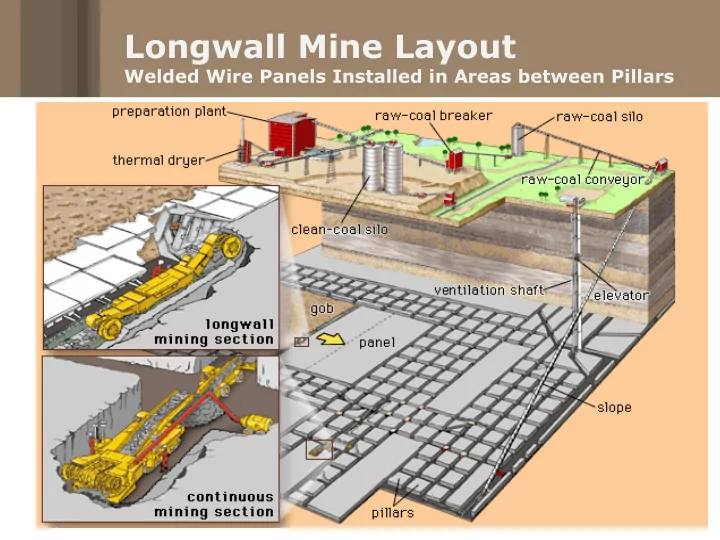
Longwall Mine Layout Welded Wire Panels Installed in Areas between Pillars 10 Gage Welded Wire Mesh TX Meshing Using Controlled Resistance Welded Wire Roof Support Current welded wire technology has been in effect and unchanged for years.


slide-1
SLIDE 1

Longwall Mine Layout

Welded Wire Panels Installed in Areas between Pillars

slide-2
SLIDE 2

10 Gage Welded Wire Mesh

slide-3
SLIDE 3

TX Meshing Using Controlled Resistance

slide-4
SLIDE 4

Welded Wire Roof Support

  • Current welded wire technology has been in effect and unchanged for

years.

  • Installed in drive-age areas for main and long-wall gate entries.
  • Installed size 4.5’ x 15’ (typical) and usually without galvanization.
  • Panels are very heavy, dangerous, labor intensive to install and subject

to transportation damage.

  • 7 year maximum life with diminishing strength from the date of install

due to acidic and high humidity conditions.

slide-5
SLIDE 5
  • $1000/hour costs are associated with entry rehabilitation after 7

years with welded wire due to corrosion.

  • Typical welded wire material loss of 10% from surface to

underground working area due to bending.

  • 10% loss of associated handling cost must also be added to

product loss

  • Heavy and often requires special material handling equipment

underground

  • Leads to back and shoulder injuries
  • When special underground handling equipment breaks

down, machine is down until it can be fixed as required by Federal Laws.

Welded Wire Panels

slide-6
SLIDE 6

TX 196 and 206 Roof Mesh

  • Designed to obsolete 10 and 8 gauge welded wire panels in long

term applications

  • Development was done with cooperation from Consol Energy and

NIOSH Testing Lab from 2011 to Present.

  • Comparative stress-strain testing done at NIOSH with actual 10 and

8 gauge 4” x 4” welded wire panels .

  • Flame-retardant polypropylene stretched to a large aperture TX

configuration.

  • Installed from a roll that unwinds from the miner/bolter or bolting

machine without brackets that result in downtime.

  • Increases speed of entry development where meshing is required by

at least 15%. No difference in speed compared to non-meshing entries.

slide-7
SLIDE 7
  • Does not interfere with proximity detection.
  • A TX196-14.5’ x 45’ mini-roll with a 9.5” diameter weighs just 40
  • lbs. TX206 roll weighs 53 lbs.
  • Roll size increases the amount of footage that can be taken

underground on a car vs. wire panels

  • White or black in color
  • Produced in jumbo rolls, 14.5’ (max) to 405’ (max) roll lengths.
  • In excess of 1 million m2 of TX196 has been installed during the

past 1.5 years.

  • Grid and Resistive Unrolling Process Patented.

TX196 and 206 Roof Mesh

slide-8
SLIDE 8

Test Procedure at NIOSH

NIOSH, Bruceton, PA Fixture table

slide-9
SLIDE 9

Test Procedure at NIOSH

  • Fixture table is secured to bottom plate of press
  • Grid is secured to fixture by a combination of channel

and/or plates on a 4’ x 4’ pattern

  • Bolts securing grid perimeter are torqued to 150 ft-lbs.
  • Press floor is raised allowing stress-strain bolt to pass

through middle grid aperture and center dome hole.

  • Nut is secured to stress-strain bolt
  • Press floor is dropped 2”/minute until grid failure
slide-10
SLIDE 10

Testing Device at NIOSH

Channel on two sides secured with plates Dome with Stress Strain Gauge

slide-11
SLIDE 11

Testing Results

6 gauge welded wire (6” plates) Design Load: 6250 lbs Stiffness: 284 lbs/in 8 gauge welded wire (6” plates) Design Load: 2900 lbs Stiffness: 250 lbs/in 8 gauge welded wire (8” plates) Design Load: 4483 lbs Stiffness: 428 lbs/in 10 gage welded wire (p and c) Design Load: 1933 lbs Stiffness: 187 lbs/in TX206 (plates and channel) Design Load: 3435 lbs Stiffness: 458 lbs/in TX196 (plates and channel) Design Load: 2000 lbs Stiffness: 193 lbs/in

The use of 6” x 6” plates used in conjunction with metal straps perpendicularly cross the mining entry is a common method to increase the efficiency of mesh by increasing the bearing surface of the primary support.

slide-12
SLIDE 12

Prefabricated TX roll

Resistive Unrolling

As machine advances, roll unwinds under resistance from foam breaking away or cable ties within roll breaking.

Foam band

slide-13
SLIDE 13

Resistance with Expandable Foam

Roll is injected from the outside with approved for underground use expandable foam. The number of rings applied will depend

  • n the specific

machinery and

  • perator

preference.

slide-14
SLIDE 14

Resistance Using Cable Ties

Cable ties are place in rows every 2-4’. The number per row depends on the application.

slide-15
SLIDE 15

Unwinder/Winder

Master roll is loaded in dispenser side…pays through a resistance bar and rerolled. Counter keeps track of the rewound length. A traversing cutting wheel is also featured. Master Roll Resistance Bar Counter and cutter wheel

slide-16
SLIDE 16

Installing Cable Ties

slide-17
SLIDE 17

Finished TX Mini-Rolls

9.5” in Diameter, TX196-40 lbs TX206-52 lbs

slide-18
SLIDE 18

Finished TX Foamed Rolls