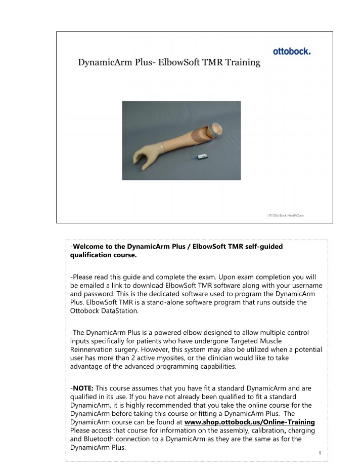
SLIDE 1
- Welcome to the DynamicArm Plus / ElbowSoft TMR self-guided
qualification course.
- Please read this guide and complete the exam. Upon exam completion you will
be emailed a link to download ElbowSoft TMR software along with your username and password. This is the dedicated software used to program the DynamicArm
- Plus. ElbowSoft TMR is a stand-alone software program that runs outside the
Ottobock DataStation.
- The DynamicArm Plus is a powered elbow designed to allow multiple control
inputs specifically for patients who have undergone Targeted Muscle Reinnervation surgery. However, this system may also be utilized when a potential user has more than 2 active myosites, or the clinician would like to take advantage of the advanced programming capabilities.
- NOTE: This course assumes that you have fit a standard DynamicArm and are
qualified in its use. If you have not already been qualified to fit a standard DynamicArm, it is highly recommended that you take the online course for the DynamicArm before taking this course or fitting a DynamicArm Plus. The DynamicArm course can be found at www.shop.ottobock.us/Online-Training Please access that course for information on the assembly, calibration, charging and Bluetooth connection to a DynamicArm as they are the same as for the DynamicArm Plus.
1
SLIDE 2 Features: This system allows for control of 3 components with 6 degrees of freedom, including elbow flexion/extension, wrist pro/supination, and hand open/close with up to 8 inputs. Each component can be assigned a single myosite or control
- input. Up to 6 sites can be used for controlling movements, and up to 2 are
available for switching between components.. Each component has the option of being controlled by 1 or 2 inputs, as well as various switching mechanisms to activate it. ElbowSoft TMR software has the ability to fine tune component operation to meet the patient‘s ability to create signals. The system can be programmed to allow for simultaneous or sequential movement of all three components, as well as the ability to assign signal dominance to either first signal wins or largest signal wins. By clicking buttons in the software, the connected components can be manually activated, which can be used for trouble-shooting system function or demonstration purposes. Each component can be turned on/off so the patient can concentrate on one component at a time. Signals can also be electronically reallocated if the wiring has been done incorrectly.
2
SLIDE 3
Hardware: The main hardware difference between DA+ and DA is the use of the 8-input MyoMaster control unit. This is the only device that plugs directly into the DA+. The 8-input MyoMaster is the master controller of the DynamicArm Plus system. All inputs, including electrodes and/or switches, will plug into this device. This device is necessary for controlling a DynamicArm Plus, and may not be used with a standard DynamicArm.
3
SLIDE 4 Wiring:
- Electrodes or other control inputs plug into ports 1-6, while any switches being
used will plug into ports A & B. This diagram indicates which ports are used for which functions.
- For wiring a wrist or wrist rotator, please refer to standard DA course, as it will
be the same.
4
SLIDE 5 Customizing Screen layout from ElbowSoft TMR software. Section 1: Signal screen shows a live visual of active EMG signals. Each individual input has its own color. Section 2: Input Configuration, is where signal dominance is chosen (First or Largest) as well as component control (Simultaneous or Sequential). Other functions available here are individual signal boost, as well as activation or deactivation of the live signal on the screen. Lastly, for each pair of signals you can activate the switch matrix when fewer than 6 myosignals are available. This allows you to program various methods of switching between components (i.e. Short co-contraction, impulse, etc). Section 3: Switch Matrix. Colors shown will then coincide with the pair of myosignals for which the switch matrix was activated. In this case, red and blue. Section 4: Joint Configuration. Allows you to manually activate components to
- veride patient signals; reallocate your inputs (for example if they were mis-
wired into the MyoMaster); and adjust the operational range of the signals (set ON threshold, and HIGH threshold) Section 5: Indicates current battery status.
5
SLIDE 6
Section 6: Allows you to save and name the current program, open a saved program, or return to the default program. NOTE: You will need the Ottobock 60X5 Bionic Link PC (Bluetooth dongle) and to install its USB drivers on your computer in order to connect the elbow to the ElbowSoft TMR software.
6
SLIDE 7 Let‘s take a look at each section of the Customizing Screen in more detail. The myograph in ElbowSoft TMR software is the same as in standard DA and most other Ottobock software. You are able to zoom, scroll, change switching thresholds, and stop/start the scrolling EMG
- Default ON threshold is 10. You can lower it to 5 and raise it to 95.
- On Threshold applies to ALL components.
- CoCo Threshold applies to both long and short co-contraction
- Upper adjustable threshold applies to 4-CH and Impulse switching
- The threshold for 2-CH control is adjustable and is accessed in the INI file,
which will be discussed later in this guide.
7
SLIDE 8 Configuration of the Input Signals: If you have already adjusted the electrode gain dial up to 6.5 and a signal is still too weak to generate desired function, you may need to boost the signal in the software.
- BOOST: offers the possibility to multiply the signal coming off of the electrode
by a factor of 0.5 to 4. 1 is the default setting and represents a “factor of 1”. In
- ther words no additional increase in signal beyond the amplification at the
electrode itself. A setting of 4 indicates a multiplication factor of 4 to a maximum boost of 400% of the signal coming off of the electrode. Additionally, lowering the slider below 1 results in a reduction of signal strength from the electrode by up to 50%. This can be useful when trying to fine tune 2 competing
- signals. Each signal has an independent boost.
Activate/deactivate signals: If the colored box is checked, the signal is active. If unchecked, the signal is
- deactivated. Each signal can be activated or deactivated independently. This is
like unplugging the input from the system. It will neither activate a component, nor will it show up on the myograph. Even when disconnected from the PC, those unchecked signals will remain OFF and provide no function. This can be useful, for example, during initial training to concentrate on control of the elbow and hand while turning off the wrist rotator without having to physically unplug
8
SLIDE 9 electrodes. If you look between the colored checked boxes, you will notice corresponding colored buttons with wave symbols. These will activate or deactivate the corresponding signal on the Myograph only, while keeping the signal active in controlling the component. The signals are enabled if the waves are dark, they are disabled if the waves are light. This allows you to concentrate on evaluating one
- r more signals at a time without being distracted by others. All signals are still
active and will produce movement of the components; the selected signals are simply not shown on the MyoGraph.
9
SLIDE 10 Further Input Configuration options:
- When 2 signals are not clearly separated, a signal dominance method needs to
be chosen. This defines the “winner” between the pair of competing signals. For each pair of signals you choose whether the winner will be the first signal to cross the ON threshold, or the signal with the largest strength. First signal wins is evaluated at the ON threshold. Whichever signal crosses the ON threshold first is the winner and the other signal is ignored. Largest signal wins is evaluated by the strength of the signal, whichever signal is the largest is the winner. If one signal falls and the other rises, the rising signal becomes the winner and the component will change direction.
10
SLIDE 11 Simultaneous or Sequential control:
- When simultaneous is chosen for any pair of signals, this will allow those
functions to occur at the same time as any other functions. For example, if simultaneous is chosen for all 3 components, then the user has the potential to
- perate a hand, wrist rotator and elbow at the same time. Please note: This type
- f function will require significant training to achieve, and the user needs to
have good separation of all signals to have predictable control of all
- components. First signal or largest signal may be chosen.
- Sequential control only allows operation of that component when other
components are not active. When sequential control is chosen, first signal wins is the automatic default; the winning signal operating the corresponding
- component. In this situation, if you would like the option of largest signals wins
(which will be grayed out), the INI file must be accessed, which is explained later in this course.
11
SLIDE 12 Creating Switching Events: When fewer than 6 electrode signals are available, any pair of signals may be chosen to create switches. This allows those 2 signals to control more than one component.
- For example, if only 4 signals are available, 2 can be used to operate the elbow,
and the other 2 can be used to operate both the hand and the powered wrist
- rotator. A switching method would be required to go between the hand and
wrist rotator. To program a switching method, click the switch matrix radio button for the desired signal pair. The color of the switch matrix will then coincide with the pair
- f myosignals for which the switch matrix was activated. In this example blue
and red signals are being used to create a switching event. You can choose a non-standard alternate pair of signals to do the switching by accessing the INI file, which is discussed later in this course. Switch options include:
- Cocontraction: (Long or short): Both signals must be fired simultaneously and
reach an adjustable threshold and relax in a defined amount of time.
- 4-Channel control allows switching of the component based on the strength
12
SLIDE 13 and speed of the signal fired. For example, for a wrist and hand, quick/strong signals would operate the wrist rotator and slow/mild signals would operate the
- hand. Thresholds for each signal are adjusted independently.
- Impulse switching allows a fast/short signal to create a switch. The required
strength and timing are adjustable using the same threshold adjustment and timer as with 4-channel control.
- The Myo-timer allows additional adjustment to co-contraction, 4-Channel, and
Impulse signals. When using co-contraction, the timer allows differentiation of a short co- contraction vs. a long co-contraction. When co-contracting, if one or both signals take longer to contract than the timer, this will be recognized as a long co-
- contraction. If both signals fall short of the timer, this will be recognized as a short
co-contraction. In the case of an impulse, the signal must cross the ON threshold and reach its upper threshold within 0.8 seconds. It must then relax before the timer expires. Failure to reach either of these parameters will prevent the signal from being recognized. With 4-channel control, there is also a time period of .8 seconds for the signal to achieve the threshold. If this threshold is reached, a quick/strong signal will be recognized and operate the proximal component. If the threshold is not reached, it will be recognized as a slow/mild signal and operate the distal component. Please note each component (elbow/wrist/hand) has it’s own column in the switch
- matrix. Any 2 components can be selected for switching by checking the
corresponding boxes. Adjusting the ON-threshold affects all signals equally by changing the strength at which signals will be recognized. The system default is 10 and can be lowered to 5. This may be useful for a patient with weaker signals by reducing the strength of signal needed to initiate function. It can also be raised to eliminate inadvertent signals from being recognized. The OFF-threshold will automatically be 50% below the selected ON-Threshold.
13
SLIDE 14 Further explanation of co-contraction programming: For co-contractions, the Myotimer determines whether a co-contraction will be recognized as a long or short co-contraction. The Myotimer activates as soon as the signal reaches its required upper threshold.
- If both signals fall below the ON threshold within the chosen amount of time,
this will be recognized as a short co-contraction. If one or both signals fall below the ON threshold beyond the chosen amount of time, this will be recognized as a long co-contraction. For users with good control of cocontraction and ability to control relaxation, this timer can be used to recognize both short and long co-contractions. This is
- useful. For example, short co-contractions could switch proximal to distal, and
long co-contractions could switch distal to proximal. This also allows the creation of stricter parameters to prevent inadvertent cocontractions from activating the system if this is an issue.
14
SLIDE 15 Use of the MyoTimer: Please note: When using 4-Channel control in DA Plus, there is an additional timer requirement that is not necessary in the standard DA. In DA Plus, 4-Channel Control has 2 adjustable parameters that must be met. One is the adjustable upper threshold, the other is the Myotimer. For example,
- nce the signal crosses the ON threshold, it has 0.8 seconds to reach the upper
- threshold. It must then be held the amount of the myotimer setting to be
considered a quick/strong signal. If the signal relaxes below the thershold before the timer expires, it is considered a slow/mild signal When an Impulse switch is selected, after crossing the ON threshold, the signal must reach its upper theshold within 0.8 seconds and relax below the ON threshold before the Myotimer expires. If the signal takes longer to relax, it is not recognized as an impulse.
15
SLIDE 16
When using both an impulse as a switch and 4 Channel for control: If impulse and 4 CH are both chosen for a pair of signals, the Myotimer can be used to improve differentiation of these signals. Setting the timer beyond the patient‘s natural impulse relaxation time allows differentiation of a control signal vs an impulse switching signal. To create a 4-Channel signal, the patient must continue to hold their signal after reaching the upper threshold beyond the set timer. Movement does not occur until the timer has expired, so a delay in component movement may be noted.
16
SLIDE 17 Using external switches: Just as in the standard DynamicArm, a digital switch or a 4-Step linear transducer (LT) may be used to switch between components.
- When using a 4-Step LT, it must be plugged into port A of the myomaster. Each
step can be assigned a specific component by checking the corresponding box. Please note not all steps need to be used. The benefit of the step transducer is that the user may select the desired component to activate in any order at any time.
- If using a digital switch, it is plugged into port B of the myomaster. Check the
boxes to activate the desired components. In this case, it only allows sequential switching between components. The switch-LT Step Timer determines how quickly the patient must activate and release the switch or LT for the change of component to occur. If either one is held too long, the change of component will not occur.
17
SLIDE 18 Activating a Switch: The left diagram illustrates the use of a 4 step LT.
- 3 different „clicks“ can be felt when the transducer is pulled, each of which is
assigned to a component. For example, LT step 2 might be assigned to the wrist
- rotator. When the patient pulls the LT to step 2 the timer starts. The signal must
then relax within the length of time set in the timer for the wrist rotator to be
- activated. Any step can be assigned to any component, depending on patient
- preference. However, it often makes sense to assign them in progression (i.e.
Step 3, elbow, step 2 wrist, step 1 hand, etc). The diagram on the right illustrates the use of a digital switch. The switch needs to be activated and released within the set amount of time programmed in the
- timer. Please note a digital switch always creates a signal of maximum strength,
it is not proportional.
18
SLIDE 19 Automatic Switching:
- If a patient wants to have the prosthesis always switch automatically from one
component to another after a set amount of time, the automatic timer can be
- used. Automatic switching can only occur between 2 components. For example,
if the wrist and hand are chosen, function will automatically switch from the wrist to the hand.
- The order of components switched is determined by the direction of the yellow
- arrows. Auto switching may occure either proximal component to distal
component, or vice versa.
- Also please note, the timer will not begin unless the first component moves,
followed by signal relaxation. Once this combination occurs, the timer starts. When the time expires, function will switch to the other component.
19
SLIDE 20 Automatic Timer Activation:
- This slide indicates how the timer is activated: When any signal in the active
component crosses the On Threshold (creates motion), then relaxes below the On Threshold, it is at this point that the timer is activated. When the set time expires, the function automatically switches to the chosen component. If audio
- r vibration alerts have been set, they will also be activated at the time of
switching.
- Unlike the standard DynamicArm, DynamicArm Plus allows you to choose a
single joint to default to. For example, if only the check box under terminal device is checked, after activating either the elbow or the wrist and relaxing, function will automatically switch to the terminal device at timer expiration
20
SLIDE 21 Creating Switching Feedback:
- You may choose either beeps or vibrations as feedback when switching
- components. These may be disabled when no longer needed for training
purposes. Start Switched Joint Selection:
- Determines the component that is active when the DA+ is turned ON
Direction of switching (switch rule)
- When creating a switching scheme, you may choose the direction of switching
by clicking on the yellow arrow: either proximal to distal switching, or distal to proximal switching is possible.
21
SLIDE 22 Choosing basic Control Modes:
- Control Modes allow you to determine how many and what type of inputs are
in control of each component, similar to the standard DynamicArm. For example: 1 electrode (1ELE); 2 electrodes (2ELE); 2 electrodes with minimal signals (ACC), etc.
- Note: under HAND, a standard program may be chosen for Ottobock basic myo
devices: SensorHand Speed, MyoHand Variplus Speed and Greifers (provided they have a black coding plug, which is standard) For the Bebionic hand, the Bebalance software is used to program the hand. Similiarly, if using another manufacturer‘s hand, you must program hand function with that manufacturer‘s software.
- When ACC is chosen for elbow control, there is a difference between how the
standard DynamicArm functions, and the DynamicArm Plus:
- With standard DynamicArm, when the signal crosses the ON threshold, the
component speed increases continuously with a constant slope until the max speed is reached. It doesn‘t matter how high above the on-threshold the signal
22
SLIDE 23 has reached.
- In the case of the DynamicArm Plus, the signal level determines the rate of speed
- increase. The higher the signal is above the on-threshold, the faster the rate of
speed increase.
- For more indepth information on the control modes, please see the DynamicArm
training course on-line
23
SLIDE 24 Activating/Deactivating components:
- A check mark in the box means the component is active. If unchecked, the
component is inactive. Signals are still displayed in the Myograph and movement range areas. This is useful for „training mode“
- This only deactivates the component when connected to the PC. When you
disconnect the PC from the DynamicArm Plus the component becomes active.
24
SLIDE 25 Allocating signals to each component function:
- By default, each signal is allocated to a specific function. For example: By
default, red is open and blue is close. However, this may be changed by checking the „Reverse“ box for a particular component.
- When using 2 control signals to control 2 components (for example wrist and
hand: 4 motions) one signal would typically be used to control open and supination (red). However, this could be changed to allow that signal to operate
- pen and pronation, etc.
- If using 2 CH control, typically the quick/strong signal will operate the wrist; a
slow/mild signal would operate the hand. However, it is possible to reverse this and have pronation or supination with slow/mild signals, and hand open or close with quick/strong signals
25
SLIDE 26 Manual activation of components:
- This feature allows testing of components by clicking on the corresponding
buttons to overide patient control.
- Note: The default speed of all components is 100%. The speed of the DA can be
changed in the INI file (explained later)
- The speed of the hand and wrist rotator can be adjusted with Myoselect, or the
corresponding software for the terminal device.
26
SLIDE 27 Adjusting Operational Range of signals:
- The sliders denote the ON Threshold and Upper Thresholds for each signal- the
- perational range. Where the upper threshold is set denotes the level of signal
required to have 100% speed. Where the ON Threshold is set, determines the level of signal required to create function in the component. For example: If cardiac rythms are an issue, or other inadvertant signals are crossing the ON Threshold, it may be raised to prevent those signals from activating a component. Note: You can affect the max speed possible of each joint by raising the upper threshold to a level that is beyond the signal strength that the patient can reach, therefore they will not be able to run the joint at full speed. This is not the intent
- f the movement range adjustments.
In some cases, despite signal boost, a user is not able to make signals reach the upper threshold. In this situation, lowering the upper threshold slider to meet the users strongest possible signal will allow the user to activate maximum speed (or maximum grip force in the case of a terminal device).
27
SLIDE 28 Operational Status Indicators:
- Bluetooth connection is indicated by a solid blue symbol. If flashing, Bluetooth
communication has not been established, or has been lost.
- Current battery charge state is indicated
28
SLIDE 29 Saving and Recalling Programs:
- When new, the DynamicArm Plus will arrive in a default program. Any change
to this program will result in a custom program being created. If you would like to save a custom program, simply click on „Save“ and give the program a name as prompted.
- To open a saved or custom program, click on the „Open“ button and choose
the program desired. It will automatically be downloaded into the Customizing screen.
- Clicking the „Default Program“ button will return the device to its default
program as when new.
29
SLIDE 30 Default Program Settings: The Default Program (new out of box) is set for the following parameters:
- 6 inputs = one input for each degree of movement: open/close;
pronate/supinate; flex/extend
- Simultaneous movement possible for all 3 components
- Largest signal wins
- Boost factor of 1: No additional boost of signal off the electrode
- Operational range 0 to 100%
- Note: Only Myobock terminal device can be programmed within the ElbowSoft
- software. All others must be programmed using MyoSelect, or thier specific
appropriate software prior to connecting to the DynamicArm Plus.
30
SLIDE 31 Using the INI file to make adjustments not possible in the Customizing screen: Steps to access the INI file
- 1.Click on save button on Elbowsoft TMR programming screen
- 2.Type in a file name and choose a location to save the file
- 3.Click on Save and the program parameters are saved in the file.
- 4.Locate the file where it was saved and right click on it, choose Open or Open
with and from the list choose notepad and click OK.
- 5.Make changes to the values as needed and then save the changes.
- 6.Return to the Elbowsoft TMR programming screen.
- 7.Click on Open, locate the file in the drop down, highlight the file and click
Open, and the modified file parameters will be loaded in the DA-Plus
- Switch channels allows you to change the pair of signals used in the switch
- matrix. By default, the software pairs channels 1 and 2; 3 and 4; 5 and 6.
However, you may create different pairs for switching, for example 1 and 6, etc.
- Joint Slope: This allows adjustment of signal smoothing. If signals tend to have
a lot of peaks or „jagged“ appearance, they may be smoothed out by the
31
SLIDE 32 software to improve movement control. The default setting is 50; the range is 1-
- 127. If set too low, it will take a long time to initiate movement when a signal is
- recognized. Joint Slope may be adjusted for all components: elbow; wrist; hand.
- 2-CH control: This allows you to set the upper threshold for 2CH control of elbow
- r wrist. This upper threshold determines the differentiation of quick/strong vs.
slow/mild.
- Adjust maximum elbow speed. Default is 100% Range is 30% to 100%
32
SLIDE 33 Signal Processing:
- This slide provides a schematic of signal flow and how they are processed.
- Signals come into the main electronics and are determined to be a control
signal or a switch input (depends on where they are plugged into the MyoMaster)
- If a signal is a switch input, it is sent through the switch matrix where a specific
component is activated, and a feedback is created.
- If a signal is a control signal, it is sent through the signal
activated/deactiveated matrix, then on to the boost matrix.
- From there, if it is determined to be a control element, it is processed according
to the set parameters: first/largest wins; simultaneous or sequential control; then it goes on to which component it is assigned to. At joint configuration, the signal is further processed to determine its operational range and direction of
- movement. Next, it is determined whether it is to be active in the software, or
visible on the screen. Finally, it is sent to control its component.
33
SLIDE 34
- This slide gives a general recommendation for the process of programming a
DynamicArm Plus, and the sequence of evaluation and adjustment.
34
SLIDE 35 Mapping of signals:
- Here is a sample mapping of active signals (post TMR surgery) and their
assigment to specific prosthetic functions. In this case, 5 seperate signals have been identified, therefore 5 motions can be controlled individually. If fewer than 6 signals are identifiable, then one or more signals will be needed for switching,
- r a separate electronic switch will need to be incorporated into the system.
- For further information on mapping signals, please see resource
attachments for download with this guide.
35
SLIDE 36 Default program:
- This screen indicates the ideal situation where 6 signals are identified and have
adequate separation. Because each of the 6 sitgnals can be assigned to a single component motion, there is no need for a switching system to be activated. Note the lack of boxes checked in the switching matrix.
36
SLIDE 37 The DynamicArm Plus comes with the following items:
- Elbow and forearm
- MyoMaster controller
- Charger
- Wrist lamination collar
- Alignment collar and uprights for attachement to socket
- Fabrication dummies
- Instructions For Use
37
SLIDE 38
38
SLIDE 39
39