
SLIDE 1
February 9, 2009 Courtesy of Arvind http:// csg.csail.mit.edu/6.375/ L03-1
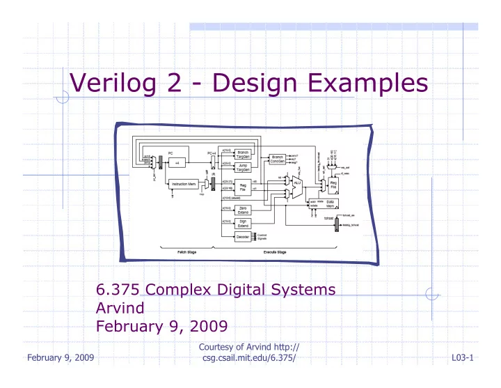
Verilog 2 - Design Examples 6.375 Complex Digital Systems Arvind - - PowerPoint PPT Presentation
Verilog 2 - Design Examples 6.375 Complex Digital Systems Arvind February 9, 2009 Courtesy of Arvind http:// February 9, 2009 csg.csail.mit.edu/6.375/ L03-1 Verilog can be used at several levels A common approach is to High-Level
February 9, 2009 Courtesy of Arvind http:// csg.csail.mit.edu/6.375/ L03-1
February 9, 2009 L03-2 Courtesy of Arvind http:// csg.csail.mit.edu/6.375/
automatic tools to synthesize a low-level gate-level model High-Level Behavioral Register Transfer Level Gate Level A common approach is to use C/C++ for initial behavioral modeling, and for building test rigs
February 9, 2009 L03-3 Courtesy of Arvind http:// csg.csail.mit.edu/6.375/
assign C_in = B_out + 1;
always @(*) begin
if (in1 == 1)
else if (in2 == 1)
end
always blocks allow more expressive control structures, though not all will synthesize default
February 9, 2009 L03-4 Courtesy of Arvind http:// csg.csail.mit.edu/6.375/
always @( posedge clk ) C_out <= C_in;
February 9, 2009 L03-5 Courtesy of Arvind http:// csg.csail.mit.edu/6.375/
wire A_in, B_in, C_in; reg A_out, B_out, C_out; always @( posedge clk ) begin A_out <= A_in; B_out <= A_out + 1; C_out <= B_out + 1; end
The order of non-blocking assignments does not matter! The effect of non-blocking assignments is not visible until the end of the “simulation tick”
February 9, 2009 L03-6 Courtesy of Arvind http:// csg.csail.mit.edu/6.375/
wire A_in, B_in, C_in; reg A_out, B_out, C_out; always @( posedge clk ) begin A_out <= A_in; B_out <= B_in; C_out <= C_in; end assign B_in = A_out + 1; assign C_in = B_out + 1;
B_in and C_in are evaluated as needed
February 9, 2009 L03-7 Courtesy of Arvind http:// csg.csail.mit.edu/6.375/
wire A_in, B_in, C_in; reg A_out, B_out, C_out; always @( posedge clk ) begin A_out <= A_in; B_out <= B_in; C_out <= C_in; assign B_in = A_out + 1; assign C_in = B_out + 1; end
Syntactically illegal
February 9, 2009 L03-8 Courtesy of Arvind http:// csg.csail.mit.edu/6.375/
wire A_in, B_in, C_in; reg A_out, B_out, C_out; always @( posedge clk ) A_out <= A_in; assign B_in = A_out + 1; always @( posedge clk ) B_out <= B_in; assign C_in = B_out + 1; always @( posedge clk ) C_out <= C_in;
Does it have the same functionality? Need to understand something about Verilog execution semantics
February 9, 2009 L03-9 Courtesy of Arvind http:// csg.csail.mit.edu/6.375/
wire A_in, B_in, C_in; reg A_out, B_out, C_out; always @( posedge clk ) begin A_out = A_in; B_out = B_in; C_out = C_in; end assign B_in = A_out + 1; assign C_in = B_out + 1;
Does it have the same functionality?
Not even close! 1 2 3 4 5
February 9, 2009 Courtesy of Arvind http:// csg.csail.mit.edu/6.375/ L03-10
February 9, 2009 L03-11 Courtesy of Arvind http:// csg.csail.mit.edu/6.375/
Active Event Queue
A B C
wire A_in, B_in, C_in; reg A_out, B_out, C_out; always @( posedge clk ) A_out <= A_in; assign B_in = A_out + 1; always @( posedge clk ) B_out <= B_in; assign C_in = B_out + 1; always @( posedge clk ) C_out <= C_in;
February 9, 2009 L03-12 Courtesy of Arvind http:// csg.csail.mit.edu/6.375/
Active Event Queue A
B C
B C 1
wire A_in, B_in, C_in; reg A_out, B_out, C_out; always @( posedge clk ) A_out <= A_in; assign B_in = A_out + 1; always @( posedge clk ) B_out <= B_in; assign C_in = B_out + 1; always @( posedge clk ) C_out <= C_in;
February 9, 2009 L03-13 Courtesy of Arvind http:// csg.csail.mit.edu/6.375/
Active Event Queue
B C 1 C 1 2
wire A_in, B_in, C_in; reg A_out, B_out, C_out; always @( posedge clk ) A_out <= A_in; assign B_in = A_out + 1; always @( posedge clk ) B_out <= B_in; assign C_in = B_out + 1; always @( posedge clk ) C_out <= C_in;
February 9, 2009 L03-14 Courtesy of Arvind http:// csg.csail.mit.edu/6.375/
February 9, 2009 L03-15 Courtesy of Arvind http:// csg.csail.mit.edu/6.375/
Active Event Queue
Non-Blocking Queue A R B R C R 1 2 A L B L C L Variables in RHS of always blocks are not updated until all inputs (e.g. LHS + dependencies) are evaluated
wire A_in, B_in, C_in; reg A_out, B_out, C_out; always @( posedge clk ) A_out <= A_in; assign B_in = A_out + 1; always @( posedge clk ) B_out <= B_in; assign C_in = B_out + 1; always @( posedge clk ) C_out <= C_in;
February 9, 2009 L03-16 Courtesy of Arvind http:// csg.csail.mit.edu/6.375/
February 9, 2009 L03-17 Courtesy of Arvind http:// csg.csail.mit.edu/6.375/
int GCD( int inA, int inB) { int done = 0; int A = inA; int B = inB; while ( !done ) { if ( A < B ) { swap = A; A = B; B = swap; } else if ( B != 0 ) A = A - B; else done = 1; } return A; }
Such a GCD description can be easily written in Behavioral Verilog It can be simulated but it will have nothing to do with hardware, i.e. it won’t synthesize.
February 9, 2009 L03-18 Courtesy of Arvind http:// csg.csail.mit.edu/6.375/
module GCD_behav#( parameter W = 16 ) ( input [W-1:0] inA, inB,
reg [W-1:0] A, B, out, swap; integer done; always @(*) begin done = 0; A = inA; B = inB; while ( !done ) begin if ( A < B ) swap = A; A = B; B = swap; else if ( B != 0 ) A = A - B; else done = 1; end
Note data dependent loop, “done”
February 9, 2009 L03-19 Courtesy of Arvind http:// csg.csail.mit.edu/6.375/
module gcdGCDUnit_behav#( parameter W = 16 ) ( input [W-1:0] inA, inB,
reg [W-1:0] A, B, out, swap; integer done; always @(*) begin done = 0; A = inA; B = inB; while ( !done ) begin if ( A < B ) swap = A; A = B; B = swap; else if ( B != 0 ) A = A - B; else done = 1; end
What does the RTL implementation need? State Less-Than Comparator Equal Comparator Subtractor
February 9, 2009 L03-20 Courtesy of Arvind http:// csg.csail.mit.edu/6.375/
idle input_available
result_data result_taken result_rdy clk reset
February 9, 2009 L03-21 Courtesy of Arvind http:// csg.csail.mit.edu/6.375/
B A = inA; B = inB; while ( !done ) begin if ( A < B ) swap = A; A = B; B = swap; else if (B != 0) A = A - B; else done = 1; End Y = A; zero? lt A sub
February 9, 2009 L03-22 Courtesy of Arvind http:// csg.csail.mit.edu/6.375/
B A sel A en B sel B en A<B B=0 zero? lt A sub
Control unit should be designed to be either busy
input or waiting for
picked up
A = inA; B = inB; while ( !done ) begin if ( A < B ) swap = A; A = B; B = swap; else if (B != 0) A = A - B; else done = 1; End Y = A;
February 9, 2009 L03-23 Courtesy of Arvind http:// csg.csail.mit.edu/6.375/
module GCDdatapath#( parameter W = 16 ) ( input clk, // Data signals input [W-1:0] operand_A, input [W-1:0] operand_B,
// Control signals (ctrl->dpath) input A_en, input B_en, input [1:0] A_sel, input B_sel, // Control signals (dpath->ctrl)
);
B
A sel A en B sel B en A < B B = 0
zero? lt A sub
February 9, 2009 L03-24 Courtesy of Arvind http:// csg.csail.mit.edu/6.375/
wire [W-1:0] B; wire [W-1:0] sub_out; wire [W-1:0] A_out; vcMux3#(W) A_mux ( .in0 (operand_A), .in1 (B), .in2 (sub_out), .sel (A_sel), .out (A_out) ); wire [W-1:0] A; vcEDFF_pf#(W) A_pf ( .clk (clk), .en_p (A_en), .d_p (A_out), .q_np (A) );
B
A sel A en B sel B en A < B B = 0
zero? lt A sub
February 9, 2009 L03-25 Courtesy of Arvind http:// csg.csail.mit.edu/6.375/
wire [W-1:0] B; wire [W-1:0] sub_out; wire [W-1:0] A_out; vcMux3#(W) A_mux ( .in0 (operand_A), .in1 (B), .in2 (sub_out), .sel (A_sel), .out (A_out) ); wire [W-1:0] A; vcEDFF_pf#(W) A_pf ( .clk (clk), .en_p (A_en), .d_p (A_out), .q_np (A) ); wire [W-1:0] B_out; vcMux2#(W) B_mux ( .in0 (operand_B), .in1 (A), .sel (B_sel), .out (B_out) ); vcEDFF_pf#(W) B_pf ( .clk (clk), .en_p (B_en), .d_p (B_out), .q_np (B) ); assign B_zero = (B==0); assign A_lt_B = (A < B); assign sub_out = A - B; assign result_data = A;
Continuous assignment combinational logic is fine Using explicit state helps eliminate issues with non-blocking assignments
February 9, 2009 L03-26 Courtesy of Arvind http:// csg.csail.mit.edu/6.375/
WAIT CALC DONE input_availble ( B = 0 ) result_taken Waiting for new input operands Swapping and subtracting Waiting for consumer to take the result reset
February 9, 2009 L03-27 Courtesy of Arvind http:// csg.csail.mit.edu/6.375/
localparam WAIT = 2'd0; localparam CALC = 2'd1; localparam DONE = 2'd2; reg [1:0] state_next; wire [1:0] state; vcRDFF_pf#(2,WAIT) state_pf ( .clk (clk), .reset_p (reset), .d_p (state_next), .q_np (state) );
Explicit state in the control logic is also a good idea! Localparams are not really parameters at all. They are scoped constants.
February 9, 2009 L03-28 Courtesy of Arvind http:// csg.csail.mit.edu/6.375/
reg [6:0] cs; always @(*) begin //Default control signals A_sel = A_SEL_X; A_en = 1'b0; B_sel = B_SEL_X; B_en = 1'b0; input_available = 1'b0; result_rdy = 1'b0; case ( state ) WAIT : ... CALC : ... DONE : ... endcase end WAIT: begin A_sel = A_SEL_IN; A_en = 1'b1; B_sel = B_SEL_IN; B_en = 1'b1; input_available = 1'b1; end CALC: if ( A_lt_B ) A_sel = A_SEL_B; A_en = 1'b1; B_sel = B_SEL_A; B_en = 1'b1; else if ( !B_zero ) A_sel = A_SEL_SUB; A_en = 1'b1; end DONE: result_rdy = 1'b1;
February 9, 2009 L03-29 Courtesy of Arvind http:// csg.csail.mit.edu/6.375/
always @(*) begin // Default is to stay in the same state state_next = state; case ( state ) WAIT : if ( input_available ) state_next = CALC; CALC : if ( B_zero ) state_next = DONE; DONE : if ( result_taken ) state_next = WAIT; endcase end WAIT CALC DONE input_availble
( B = 0 )
result_taken reset
February 9, 2009 L03-30 Courtesy of Arvind http:// csg.csail.mit.edu/6.375/
B
A sel A en B sel B en A < B B = 0
zero? lt A sub
Generic Test Source Generic Test Sink