CS6710 Tool Suite Verilog-XL Synthesis and Place & Route - - PDF document

cs6710 tool suite
SMART_READER_LITE
LIVE PREVIEW

CS6710 Tool Suite Verilog-XL Synthesis and Place & Route - - PDF document

CS6710 Tool Suite Verilog-XL Synthesis and Place & Route Synopsys Behavioral Design Compiler Verilog Structural Synopsys design compiler Verilog Cadence Cadence SOC Encounter Your SOC Library Encounter Circuit Verilog-XL CSI


slide-1
SLIDE 1

1 Synthesis and Place & Route

Synopsys design compiler Cadence SOC Encounter
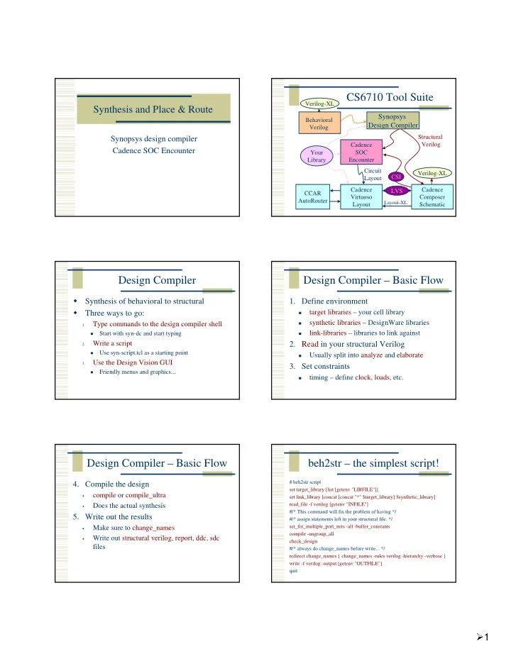
CS6710 Tool Suite

Synopsys Design Compiler

Cadence SOC Encounter Cadence Composer Schematic Cadence Virtuoso Layout CCAR AutoRouter Your Library Verilog-XL Verilog-XL Behavioral Verilog Structural Verilog Circuit Layout LVS

Layout-XL

CSI

Design Compiler

  • Synthesis of behavioral to structural
  • Three ways to go:

1.

Type commands to the design compiler shell

  • Start with syn-dc and start typing

2.

Write a script

  • Use syn-script.tcl as a starting point

3.

Use the Design Vision GUI

  • Friendly menus and graphics...

Design Compiler – Basic Flow

  • 1. Define environment
  • target libraries – your cell library
  • synthetic libraries – DesignWare libraries
  • link-libraries – libraries to link against
  • 2. Read in your structural Verilog
  • Usually split into analyze and elaborate
  • 3. Set constraints
  • timing – define clock, loads, etc.

Design Compiler – Basic Flow

  • 4. Compile the design
  • compile or compile_ultra
  • Does the actual synthesis
  • 5. Write out the results
  • Make sure to change_names
  • Write out structural verilog, report, ddc, sdc

files

beh2str – the simplest script!

# beh2str script set target_library [list [getenv "LIBFILE"]] set link_library [concat [concat "*" $target_library] $synthetic_library] read_file -f verilog [getenv "INFILE"] #/* This command will fix the problem of having */ #/* assign statements left in your structural file. */ set_fix_multiple_port_nets -all -buffer_constants compile -ungroup_all check_design #/* always do change_names before write... */ redirect change_names { change_names -rules verilog -hierarchy -verbose } write -f verilog -output [getenv "OUTFILE"] quit

slide-2
SLIDE 2

2

.synopsys_dc.setup

set SynopsysInstall [getenv "SYNOPSYS"] set search_path [list . \ [format "%s%s" $SynopsysInstall /libraries/syn] \ [format "%s%s" $SynopsysInstall /dw/sim_ver] \ ] define_design_lib WORK -path ./WORK set synthetic_library [list dw_foundation.sldb] set synlib_wait_for_design_license [list "DesignWare-Foundation"] set link_library [concat [concat "*" $target_library] $synthetic_library] set symbol_library [list generic.sdb]

What beh2str leaves out...

Timing!

No clock defined so no target speed No input drive defined so assume infinite drive No output load define so assume something

syn-script.tcl

/uusoc/facility/cad_common/local/class/6710/synopsys #/* search path should include directories with memory .db files */ #/* as well as the standard cells */ set search_path [list . \ [format "%s%s" SynopsysInstall /libraries/syn] \ [format "%s%s" SynopsysInstall /dw/sim_ver] \ !!your-library-path-goes-here!!] #/* target library list should include all target .db files */ set target_library [list !!your-library-name!!.db] #/* synthetic_library is set in .synopsys_dc.setup to be */ #/* the dw_foundation library. */ set link_library [concat [concat "*" $target_library] $synthetic_library]

syn-script.tcl

#/* below are parameters that you will want to set for each design */ #/* list of all HDL files in the design */ set myfiles [list !!all-your-files!! ] set fileFormat verilog ;# verilog or VHDL set basename !!basename!! ;# Name of top-level module set myclk !!clk!! ;# The name of your clock set virtual 0 ;# 1 if virtual clock, 0 if real clock #/* compiler switches... */ set useUltra 1 ;# 1 for compile_ultra, 0 for compile #mapEffort, useUngroup are for #non-ultra compile... set mapEffort1 medium ;# First pass - low, medium, or high set mapEffort2 medium ;# second pass - low, medium, or high set useUngroup 1 ;# 0 if no flatten, 1 if flatten

syn-script.tcl

#/* Timing and loading information */ set myperiod_ns !!10!! ;# desired clock period (sets speed goal) set myindelay_ns !!0.5!! ;# delay from clock to inputs valid set myoutdelay_ns !!0.5!! ;# delay from clock to output valid set myinputbuf !!invX4!! ;# name of cell driving the inputs set myloadcell !!UofU_Digital/invX4/A!! ;# pin that outputs drive set mylibrary !!UofU_Digital!! ;# name of library the cell comes from #/* Control the writing of result files */ set runname struct ;# Name appended to output files

syn-script.tcl

#/* the following control which output files you want. They */ #/* should be set to 1 if you want the file, 0 if not */ set write_v 1 ;# compiled structural Verilog file set write_db 0 ;# compiled file in db format (obsolete) set write_ddc 0 ;# compiled file in ddc format (XG-mode) set write_sdf 0 ;# sdf file for back-annotated timing sim set write_sdc 1 ;# sdc constraint file for place and route set write_rep 1 ;# report file from compilation set write_pow 0 ;# report file for power estimate

slide-3
SLIDE 3

3

syn-script.tcl

# analyze and elaborate the files analyze -format $fileFormat -lib WORK $myfiles elaborate $basename -lib WORK -update current_design $basename # The link command makes sure that all the required design # parts are linked together. # The uniquify command makes unique copies of replicated modules. link uniquify # now you can create clocks for the design if { $virtual == 0 } { create_clock -period $myperiod_ns $myclk } else { create_clock -period $myperiod_ns -name $myclk }

syn-script.tcl

# Set the driving cell for all inputs except the clock # The clock has infinite drive by default. This is usually # what you want for synthesis because you will use other # tools (like SOC Encounter) to build the clock tree (or define it by hand). set_driving_cell -library $mylibrary -lib_cell $myinputbuf \ [remove_from_collection [all_inputs] $myclk] # set the input and output delay relative to myclk set_input_delay $myindelay_ns -clock $myclk \ [remove_from_collection [all_inputs] $myclk] set_output_delay $myoutdelay_ns -clock $myclk [all_outputs] # set the load of the circuit outputs in terms of the load # of the next cell that they will drive, also try to fix hold time issues set_load [load_of $myloadcell] [all_outputs] set_fix_hold $myclk

syn-script.tcl

# now compile the design with given mapping effort # and do a second compile with incremental mapping # or use the compile_ultra meta-command if { $useUltra == 1 } { compile_ultra } else { if { $useUngroup == 1 } { compile -ungoup_all -map_effort $mapEffort1 compile -incremental_mapping -map_effort $mapEffort2 } else { compile -map_effort $mapEffort1 compile -incremental_mapping -map_effort $mapEffort2 } }

syn-script.tcl

# Check things for errors check_design report_constraint -all_violators set filebase [format "%s%s" [format "%s%s" $basename "_"] $runname] # structural (synthesized) file as verilog if { $write_v == 1 } { set filename [format "%s%s" $filebase ".v"] redirect change_names { change_names -rules verilog -hierarchy - verbose } write -format verilog -hierarchy -output $filename } # write the rest of the desired files... then quit

Using Scripts

Modify syn-script.tcl or write your own syn-dc –f scriptname.tcl Make sure to check output!!!!

Using Design Vision

You can do all of these commands from the design vision gui if you like syn-dv Follow the same steps as the script

Set libraries in your own .synopsys_dc.setup analyze/elaborate define clock and set constraints compile write out results

slide-4
SLIDE 4

4

Setup

File ->Setup

analyze/elaborate

File -> Analyze File ->Elaborate

Look at results... Define clock

attributes -> specify clock Also look at other attributes...

Compile

Design -> Compile Ultra

Timing Reports

Timing -> Report Timing Path

slide-5
SLIDE 5

5

Write Results

File -> Save As... change_names

Or, use syn-dv after script...

syn-dc –f mips.tcl results in .v, .ddc, .sdc, .rep files Read the .ddc file into syn-dv and use it to explore timing...

syn-dv with mips_struct.v

File -> Read

Endpoint slack...

Timing -> Endpoint Slack

Path Slack

Timing -> Path Slack

SOC Encounter

Need structural Verilog, .sdc, library.lib, library.lef make a new dir for soc... <design>.conf is also very helpful

use UofU_soc.conf as starting point.

Usual warnings about scripting... UofU_opt.tcl is the generic script

.../local/class/6710/cadence/SOC

cad-soc

slide-6
SLIDE 6

6

SOC Flow

  • 1. Import Design
  • .v, .sdc, .lib, .lef – can put this in a .conf
  • 2. Power plan
  • rings, stripes, row-routing (sroute)
  • 3. Placement
  • place cells in the rows
  • 4. Timing optimization – preCTS

SOC Flow

  • 5. Synthesize clock tree
  • use your buf or inv footprint cells
  • 6. timing optimization – postCTS
  • 7. global routing
  • NanoRoute
  • 8. timing optimization – postRoute
  • 9. Add filler cells
  • 10. Write out results
  • .def, _soc.v, .spef, .sdc, .lef

Design Import Floorplan

Specify -> Floorplan

Power Rings and Stripes

Power -> Power Planning

Sroute to connect things up

Route -> Sroute

slide-7
SLIDE 7

7

Place cells

Place -> Place cells...

pre-CTS timing optimization

Timing -> Optimization

Clock Tree Synthesis

clock -> create clock tree spec clock -> specify clock tree clock ->Synthesize clock tree

Display Clock Tree post-CTS optimization NanoRoute

Route -> NanoRoute -> Route

slide-8
SLIDE 8

8

Routed circuit postRoute optimization

Timing -> Optimization

Add Filler

Place -> Filler -> Add...

Write Results...

Design -> Save -> Netlist Design -> Save -> DEF

Encounter Scripting

Usual warnings – know what’s going on! Use UofU_opt.tcl as a starting point SOC has a floorplanning stage that you may want to do by hand

write another script to read in the floorplan and

go from there...

Use encounter.cmd to see the text versions of what you did in the GUI...

UofU_opt.tcl

# set the basename for the config and floorplan files. This # will also be used for the .lib, .lef, .v, and .spef files... set basename “mips" # set the name of the footprint of the clock buffers # in your .lib file set clockBufName inv # set the name of the filler cells - you don't need a list # if you only have one set fillerCells FILL #set fillerCells [list FILL FILL2]

slide-9
SLIDE 9

9

UofU_opt.tcl

############################################################# # You may not have to change things below this line - but check! # # You may want to do floorplanning by hand in which case you # have some modification to do! ############################################################# # Set some of the power and stripe parameters - you can change # these if you like - in particular check the stripe space (sspace) # and stripe offset (soffset)! set pwidth 9.9 set pspace 1.8 set swidth 4.8 set sspace 249 set soffset 126

UofU_opt.tcl

# Import design and floorplan # If the config file is not named $basename.conf, edit this line. loadConfig $basename.conf 0 commitConfig # Make a floorplan - this works fine for projects that are all # standard cells and include no blocks that need hand placement... setDrawMode fplan floorPlan -site core -r 1.0 0.70 30.0 30.0 30.0 30.0 fit # Save deisgn so far saveDesign "fplan.enc" saveFPlan [format "%s.fp" $basename]

UofU_opt.tcl

# Make power and ground rings - $pwidth microns wide with $pspace # spacing between them and centered in the channel addRing -spacing_bottom $pspace -width_left $pwidth -width_bottom $pwidth -width_top $pwidth -spacing_top $pspace -layer_bottom metal1 -center 1 -stacked_via_top_layer metal3 -width_right $pwidth - around core -jog_distance $pspace -offset_bottom $pspace -layer_top metal1 -threshold $pspace -offset_left $pspace -spacing_right $pspace - spacing_left $pspace -offset_right $pspace -offset_top $pspace - layer_right metal2 -nets {gnd! vdd! } -stacked_via_bottom_layer metal1 - layer_left metal2

UofU_opt.tcl

# Make Power Stripes. This step is optional. If you keep it in remember to # check the stripe spacing (set-to-set-distance = $sspace) # and stripe offset (xleft-offset = $soffset)) addStripe -block_ring_top_layer_limit metal3 -max_same_layer_jog_length 3.0

  • snap_wire_center_to_grid Grid -padcore_ring_bottom_layer_limit metal1
  • set_to_set_distance $sspace -stacked_via_top_layer metal3
  • padcore_ring_top_layer_limit metal3 -spacing $pspace -xleft_offset $soffset
  • merge_stripes_value 1.5 -layer metal2 -block_ring_bottom_layer_limit metal1
  • width $swidth -nets {gnd! vdd! } -stacked_via_bottom_layer metal1

# # Use the special-router to route the vdd! and gnd! nets sroute -jogControl { preferWithChanges differentLayer } # # Save the design so far saveDesign "pplan.enc"

UofU_opt.tcl

Read the script... place pre-CTS optimization clock tree synthesis post-CTS optimization routing post-ROUTE optimization add filler write out results

Read back to icfb

File -> Import -> DEF

slide-10
SLIDE 10

10

Change abstract to layout cellviews

Edit -> Search DRC, Extract

Import Verilog

File -> Import -> Verilog LVS...

Schematic view LVS Result

Yay!

Summary

Behavioral -> structural -> layout Can be automated by scripting, but make sure you know what you’re doing

  • n-line tutorials for TCL

Google “tcl tutorial” Synopsys documentation for design_compiler encounter.cmd (and documentation) for SOC

End up with placed and routed core layout

  • r BLOCK for later use...