using STAR-CCM+ Chair of Structural Mechanics and Vehicle - - PowerPoint PPT Presentation

using star ccm chair of structural mechanics and vehicle
SMART_READER_LITE
LIVE PREVIEW

using STAR-CCM+ Chair of Structural Mechanics and Vehicle - - PowerPoint PPT Presentation

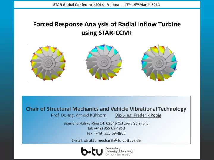
STAR Global Conference 2014 - Vienna - 17 th -19 th March 2014 Forced Response Analysis of Radial Inflow Turbine using STAR-CCM+ Chair of Structural Mechanics and Vehicle Vibrational Technology Prof. Dr.-Ing. Arnold Khhorn Dipl.-Ing.


slide-1
SLIDE 1

Chair of Structural Mechanics and Vehicle Vibrational Technology

  • Prof. Dr.-Ing. Arnold Kühhorn

Dipl.-Ing. Frederik Popig

Siemens-Halske-Ring 14, 03046 Cottbus, Germany Tel: (+49) 355 69-4853 Fax: (+49) 355 69-4805 E-mail: strukturmechanik@tu-cottbus.de STAR Global Conference 2014 - Vienna - 17th-19th March 2014

Forced Response Analysis of Radial Inflow Turbine using STAR-CCM+

slide-2
SLIDE 2

2

2 3

Content

Introduction Forced response analysis Prediction of modal forcing using STAR-CCM+ Prediction of aerodynamic damping using STAR-CCM+ Summary

4 5 1

slide-3
SLIDE 3

3

4 5

Introduction

State of the art in radial inflow turbine design: blisk (blade integrated disk) Advantage: Disadvantage: Increased efficiency Low mechanical damping Sensitive to mistuning Fundamental problems:

  • Low and high engine order excitation
  • Mistuning
  • Modeling of Fluid-Structure-Interaction
  • Identification of significant aerodynamic influences on the vibration behavior

Motivation: Accurate prediction of tuned blisk vibrations with low computational cost Exact simulation of aerodynamic interaction essential

1

2 3 Determination of aeroelastic parameters via uncoupled approaches using STAR-CCM+ Tuned Modeshape Mistuned Modeshape

slide-4
SLIDE 4

4

4 5

Forced Response Analyses – Basics

1

2

3

E m 2 m

f q ω q D q      

resonance) 1(at ω Ω η , ω D 2 f ˆ q x

mod 2 i 0, i m, E i m, max i, max i, max i, max i,

   

e

φ φ

 

2 2 i m, 2 2 2 i 0, E i m, i m, 2 i 0, E i m, i

η D 4 ) η (1 1 ω f ˆ D η, V ω f ˆ q      

i

φ

i

f

Abaqus Modal transformed equation of motion: (1) Modal frequency response function: (2) Maximum physical displacement : (3) depends on

  • Structural operating conditions
  • Modeshape:
  • Eigenfrequency :
  • Aerodynamic operating conditions
  • Modal excitation force :
  • Aerodynamic damping:

E i m,

f ˆ

i m,

D STAR-CCM+ How can we use STAR-CCM+ to estimate aerodynamic damping and forcing? Xmax Frequency response function

slide-5
SLIDE 5

5

Isentropic efficiency Torsional moment 4 5

Forced Response Analyses – Process

1

2

3 Steady State CFD - Analysis

  • Starting point: CFD-Solution after grid study

Setup configuration:

  • Multi bladerow with mixing plane
  • Reynolds-Averaged Navier Stokes Equations (RANS)
  • Spalart-Allmaras Turbulence Model
  • Single passage rotor with periodic boundaries

→ Validation: comparison against measurement data of performance test

pS (x,y,z) TS (x,y,z) Steady State CFD FEM Unsteady State CFD φi,fi Aerodynamic Damping: Aerodynamic Forcing:

slide-6
SLIDE 6

6

4 5 1

2

3 FEM-Analysis

  • Abaqus
  • Cyclic-symmetry model containing blade, disc and shaft sector
  • Application of rotational speed, pressure and temperature distributions

Results: → Nodal diameter map → Modeshapes , Eigenfrequencies

pS (x,y,z) TS (x,y,z) Steady State CFD FEM Unsteady State CFD φi,fi Aerodynamic Damping: Aerodynamic Forcing:

Forced Response Analyses – Process

i

φ

i

f

Nodal diameter map ND vs. EO diagram

BTW FTW BTW FTW BTW FTW BTW FTW BTW FTW BTW – Backward Travelling Wave FTW – Forward Travelling Wave

slide-7
SLIDE 7

7

4 5 1

2

3 Unsteady State CFD - Analysis

  • Starting point: Steady State CFD + FEM Solution
  • Requirements for application of unidirectional methods:

 Small vibration amplitudes  Big blade mass ratio

  • Verification of aerodynamic interaction by modeling of the

whole turbine system including

  • Volute
  • Nozzle guide vane
  • Radial inflow turbine

φi,fi pS (x,y,z) TS (x,y,z) Steady State CFD FEM Unsteady State CFD Aerodynamic Damping: Aerodynamic Forcing:

Forced Response Analyses – Process

Contourplot: Gradient of Density

slide-8
SLIDE 8

8

4 5

Forced Response Analyses – Process

1

2

3

φi,fi pS (x,y,z) TS (x,y,z) Steady State CFD FEM Unsteady State CFD Aerodynamic Damping: Aerodynamic Forcing:

  • Aerodynamic damping estimation for travelling wave modes1:
  • Determination of aeroelastic eigenvalues:

(5) (6) (7)

  • Applicable unidirectional methods:
  • Aerodynamic Influence Coefficients Method (AIC-Method)1
  • One simulation per blademode/operating condition
  • Partial or full assembly model
  • Applicable to harmonic balance or time-accurate solver
  • Harmonic Balance Flutter (HBF-Method)
  • One simulation per ND → (2·NDmax+1) computations per blademode/operating condition
  • Single passage model, Phase-lag boundary conditions

1 [Crawley1987]

2 σ σ 2 , 1 , a,σ a,σ a,σ a,σ

n n n n n n

ω C ˆ λ iω δ λ      

   

Im σ a, Re σ a, σ σ a, σ a,

n n n n n

λ λ ω δ D   

blades

  • f

number

  • dd

N , 2 1 N ND blades

  • f

number even N , 2 N ND ND n ND , N πn 2 σ

MAX MAX MAX MAX n

        

slide-9
SLIDE 9

9

  • Time history of modal excitation force for mode i:

(7)

  • Discrete Fourier Transformation:

4 5

Forced Response Analyses – Process

1

2

3

φi,fi pS (x,y,z) TS (x,y,z) Steady State CFD FEM Unsteady State CFD Aerodynamic Damping: Aerodynamic Forcing:

     

 

      

Cells

N j 1 j j T j i, j A T i E i m,

A t p dA t p t f n φ n φ

 

N πnk 2 i 1 N k m E n m,

e kΔ f N 1 f

  

 

t Harmonic amplitudes of modal forcing Modal force timehistory

slide-10
SLIDE 10

10

Comparison of unsteady torsional moment 4 5

Modal forcing simulation - setup

1 2

3

Version: STAR-CCM+ 8.04.011 Configuration:

  • Implicit unsteady solver
  • Mesh: STAR-CCM+ polyeder (14.4e6 cells)
  • Direct interface to ensure aerodynamic interaction
  • Rigid rotor blades (non-vibrating)
  • Reynolds-Averaged Navier-Stokes Equations (RANS)
  • Spalart-Allmaras Turbulence model
  • User defined library to store:
  • Unsteady pressure for each partition at each timestep
  • Partitioning information of rotor blades
  • Validation of user defined functions:
  • Comparison of unsteady torsional moment

Model containing volute, nozzle guide vane and radial inflow turbine

slide-11
SLIDE 11

11

4 5

Modal forcing simulation - setup

1 2

3

Example: Mode 6 / CSM 6 / E0 18

  • Modeshape interpolation:
  • Importing Abaqus result file
  • STAR-CCM+ surface mapping
  • External fortran postprocessing routines for
  • Assembling pressure data
  • Calculating modal forces

FEM - modeshape Modal sector force time history Harmonic amplitudes of modal forcing Interpolated modeshape

slide-12
SLIDE 12

12

4

5

Aerodynamic damping simulation - setup

1 2 3 Approach 1: AIC-method - unsteady time accurate solver Example: Mode 1/ CSM 6 / EO18

  • Model: Full-Assembly, reflecting inlet/exit boundaries
  • Motion specification: morphing in rotating reference frame
  • Solver : Implicit unsteady
  • Coupled Flow model
  • Reynolds-Averaged Navier-Stokes Equations (RANS)
  • Spalart-Allmaras Turbulence model
  • User defined field functions to calculate modal forces needed for

calculation of AIC’s and damping

150 ycle vibrationc per timesteps

  • f

number n , f 1 n 1 Δt

Cycle mode Cycle

   

FE-Modeshape Interpolated Modeshape CFD-Model Vibrating blade Rigid blades

slide-13
SLIDE 13

13

Relative Modal Forces

Aerodynamic damping simulation - setup

4

5 1 2 3

  • Calculation of travelling wave mode coefficents

(5)

  • Calculation of aerodynamic influence coefficients

(6)

i S i m, i

q ˆ f ˆ L 

Blade 0:L0

N πin 2 j 1 N i i S σ m, σ

e L ˆ q ˆ f ˆ C ˆ

n n

  

 

Relative Aerodynamic Influence Coefficients

slide-14
SLIDE 14

14

Relative Modal Forces

Aerodynamic damping simulation - setup

4

5 1 2 3

  • Calculation of travelling wave mode coefficents

(5)

  • Calculation of aerodynamic influence coefficients

(6)

i S i m, i

q ˆ f ˆ L 

Blade 0:L0 Blade 1: L1

N πin 2 j 1 N i i S σ m, σ

e L ˆ q ˆ f ˆ C ˆ

n n

  

 

Relative Aerodynamic Influence Coefficients

slide-15
SLIDE 15

15

Relative Modal Forces

Aerodynamic damping simulation - setup

4

5 1 2 3

  • Calculation of travelling wave mode coefficents

(5)

  • Calculation of aerodynamic influence coefficients

(6)

i S i m, i

q ˆ f ˆ L 

Blade 0:L0 Blade 1: L1 Blade 2: L2

N πin 2 j 1 N i i S σ m, σ

e L ˆ q ˆ f ˆ C ˆ

n n

  

 

Relative Aerodynamic Influence Coefficients

slide-16
SLIDE 16

16

Relative Modal Forces

Aerodynamic damping simulation - setup

4

5 1 2 3

  • Calculation of travelling wave mode coefficents

(5)

  • Calculation of aerodynamic influence coefficients

(6)

i S i m, i

q ˆ f ˆ L 

Blade 0:L0 Blade 1: L1 Blade 2: L2

N πin 2 j 1 N i i S σ m, σ

e L ˆ q ˆ f ˆ C ˆ

n n

  

 

Blade -1:LN-1 Relative Aerodynamic Influence Coefficients

slide-17
SLIDE 17

17

Relative Modal Forces

Aerodynamic damping simulation - setup

4

5 1 2 3

  • Calculation of travelling wave mode coefficents

(5)

  • Calculation of aerodynamic influence coefficients

(6)

i S i m, i

q ˆ f ˆ L 

Blade 0:L0 Blade 1: L1 Blade 2: L2 Blade -1:LN-1 Blade -2:LN-2

N πin 2 j 1 N i i S σ m, σ

e L ˆ q ˆ f ˆ C ˆ

n n

  

 

Relative Aerodynamic Influence Coefficients

slide-18
SLIDE 18

18

Relative Modal Forces

Aerodynamic damping simulation - setup

4

5 1 2 3

  • Calculation of travelling wave mode coefficents

(5)

  • Calculation of aerodynamic influence coefficients

(6)

i S i m, i

q ˆ f ˆ L 

N πin 2 j 1 N i i S σ m, σ

e L ˆ q ˆ f ˆ C ˆ

n n

  

 

Blade 0:L0 Blade 1: L1 Blade 2: L2 Blade -1:LN-1 Blade -2:LN-2 Relative Aerodynamic Influence Coefficients

slide-19
SLIDE 19

19

Aerodynamic damping simulation - setup

4

5 1 2 3

  • Calculation of travelling wave mode coefficents

(5)

  • Calculation of aerodynamic influence coefficients

(6)

i S i m, i

q ˆ f ˆ L 

N πin 2 j 1 N i i S σ m, σ

e L ˆ q ˆ f ˆ C ˆ

n n

  

 

Aerodynamic damping ratio Blade 0:L0 Blade 1: L1 Blade 2: L2 Blade -1:LN-1 Blade -2:LN-2 Relative Aerodynamic Influence Coefficients

slide-20
SLIDE 20

20

4

5 1 2 3

Aerodynamic damping simulation - setup

Approach 2: AIC-method - harmonic balance solver

  • Model: Full-Assembly, non-reflecting inlet/exit boundaries
  • Motion specification : morphing in rotating reference frame
  • Solver: Harmonic balance (1 mode)
  • Reynolds-Averaged Navier-Stokes Equations (RANS)
  • HB Standard Spalart-Allmaras Turbulence model
  • User defined field functions to calculate complex modal forces:

     

 

      

A j j T j i, j A T i E i m,

A ω p dA ω p ω f n φ n φ

Aerodynamic damping ratio Relative Aerodynamic Influence Coefficients

slide-21
SLIDE 21

21

Aerodynamic damping ratio for 1 ND

4

5 1 2 3 Approach 3: Harmonic balance flutter

  • Model: Single passage, non-reflecting inlet/exit boundaries
  • Motion specification : morphing in rotating reference frame
  • Solver: Harmonic balance flutter (3 modes)
  • Reynolds-Averaged Navier-Stokes Equations (RANS)
  • HB Standard Spalart-Allmaras Turbulence model
  • User defined field functions to calculate complex modal forces and aerodynamic damping

Aerodynamic damping simulation - setup

Aerodynamic damping ratio

slide-22
SLIDE 22

22

4

5 1 2 3

Aerodynamic damping simulation - result

Approach CPU*Time [h] (A) Harmonic balance flutter ≈ 120 h (10 ND) (B) AIC, Implicit unsteady solver ≈ 1200 h (C) AIC, Harmonic balance solver ≈ 500 h Comparison:

  • Good agreement between harmonic balance flutter and harmonic balance AIC
  • Significant deviations between time-accurate and harmonic balance solutions
  • Comparable range of damping for all 3 methods
  • Harmonic balance flutter most efficient, but ND-3/ND-4 diverged
slide-23
SLIDE 23

23

4

5

Summary

1 2 3

  • Application of unidirectional methods to STAR-CCM+ (8.04.011) successful
  • Modal forcing prediction: implicit unsteady solver
  • Aerodynamic damping prediction via AIC method :

(A) implicit unsteady solver with morphing motion (B) harmonic balance solver

  • Non-reflecting boundary conditions not applicable with implicit unsteady solver
  • Good agreement between results of harmonic balance flutter and harmonic balance AIC
  • HBF most effective, but sometimes tends to diverge
slide-24
SLIDE 24

24

Thank you for your attention!

Forced Response Analysis of Radial Inflow Turbine

  • Prof. Dr.-Ing. Arnold Kühhorn

Dipl.-Ing. Frederik Popig

Chair of Structural Mechanics & Vehicle Vibrational Technology, BTU Cottbus Acknowledgement: The presented work has been supported by the MAN Diesel & Turbo SE company.

slide-25
SLIDE 25

25

Reference list

[Giersch12] Giersch, T. , Hönisch, P., Beirow. B., Kühhorn, A.: Forced response analysis of mistuned radial inflow

  • turbine. Proceedings of ASME Turbo Expo 2012, Copenhagen, Denmark: Paper GT2012-69556.

[Nipkau11] Nipkau, J.: Analysis of Mistuned Blisk Vibrations Using a Surrogate Lumped Mass Model with Aerodynamic Influences. Dissertation. BTU Cottbus, 2011. ISBN: 978-3-8440-0302-4. [Crawley87] Crawley, E.F.: Aeroelastic Formulation for Tuned and Mistuned Rotors. In M.F. Platzer, F.O. Carta(Editor): AGARD Manual on Aeroelasticity in Axial Flow Turbomachines (Vol2) – Structural Dynamics and Aeroelasticity, pages 19-1 – 19-24. Specialised Printing Services Limited, Loughton, Essex,1987.