SLIDE 1
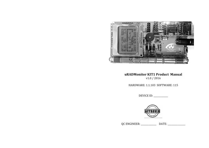
uRADMonitor KIT1 Product Manual
v1.0 / 2016 HARDWARE: 1.1.103 SOFTWARE: 115 DEVICE ID: _____________ QC ENGINEER: ______________ DATE: ________________
SLIDE 2 Congratulations on purchasing this excellent radiation dosimeter! You are now part of an ambitious global project that we call the
- uRADMonitor. Some information to help you get started is provided in
this manual and more is available
http://www.uradmonitor.com .
Summary
The uRADMonitor network 1 uRADMonitor KIT1 1 Dosimeter vs. Monitor 1 Soldering the unit 1 Connecting and starting your KIT1 6 The user interface and the main button 6 The speaker 7 The backlight 8 The watchdog 8 The alarm 8 The extension port 8 Upgrading the firmware 9 Accessing the data 10 uRADMonitor API 12 The mobile application 13 Troubleshooting 14 Frequently asked questions 14 Disclaimer 16 Warranty and support 16 Contact 17
The uRADMonitor network
The uRADMonitor project is a global array of network connected monitoring stations, focused
continuous Environmental
- Surveillance. Its purpose is to generate fully transparent open data,
used to assert the quality of our environment. Having a network that is composed of identical hardware makes the readings easily comparable. Finally, having multiple units covering the major location on the planet helps understanding the variation trends and the causes of the harmful factors being monitored, illustration pollution more like a phenomenon.
uRADMonitor KIT1
There are several uRADMonitor detectors. Your unit is called the KIT1, and is a versatile Radiation dosimeter that can be used both as a mobile detector and as a fixed monitoring station. It is released as Open Source, with complete specs publicly available. If you purchased an assembled unit, it will be usable out of the box, if your unit came as a solderable kit, you'll need to assemble it first.
Dosimeter vs. Monitor
Monitoring radiation brings certain advantages over simply using a handheld unit occasionally. First it's the capability of identifying the radiation trend, due to long term measurements, and taking action in regards to the evolution of numbers rather than not knowing how to interpret short time readings. Then with long term continuous monitoring we get a clue even on low level changes that often evade portable localized readings (unless the levels are higher). Finally having an automated system monitoring radiation 24/7 results in keeping you informed all the time, not only on occasional situations like when using a handheld for an isolated check.
Soldering the unit
If your unit comes as a kit, you'll need to assemble it before using. Please use the following diagrams, and the tutorials on the website. 1
SLIDE 3
The PCB full view The PCB holes only The SBM-20 Geiger tube is fragile. Handle it with care! 2 3
SLIDE 4
Qty Value Device Parts 1 0 / 3K R-EU_0204/7 R13 1 1N4148 1N4148DO35-7 D7 1 2.2K R-EU_0204/7 R7 1 2.2mH L-EU0207/10 L1 1 8Mhz XTAL/S quartz Q1 4 10K R-EU_0204/7 R2, R8, R14, R15 2 10M R-EU_0204/7 R3, R5 3 10nF/1KV C5/3 C6, C10, C11 1 15nF C2.5/2 C7 2 22uF 25V CPOL-EUE2-5 C3, C4 4 33pF C2.5/2 C1, C2, C8, C9 1 47K R-EU_0204/7 R4 4 100 R-EU_0204/7 R1, R9, R10, R11 1 100K R-EU_0204/7 R12 1 100nF C2.5/2 C5 1 220K R-EU_0204/7 R6 1 ATMEGA328P ATMEGA328P DIP-28 ATMEGA328P 3 BYV26E BYV26E Fast diode D1, D2, D3 1 DC IN JACK 2.1MMJACKTHM DC_IN_JACK 3 Fuse connector 6mm GEIGER_CONNECTOR CONNECTOR1, CONNECTOR2, CONNECTOR3 1 ISP_PROGRAMMER MA05-2 5x2 Male Pins SV1 1 LM1117_3.3V LD117AV IC1 1 MPSA42 MPSA42 T1 1 Momentary switch TAC_SWITCHPTH S2 1 NOKIA_5110_LCD connectors 1x8 Female Pins 2 sets U$1 3 PN2222A PN2222A T2, T4, T5 4 5
SLIDE 5 Connecting and starting your KIT1
Connect the uRADMonitor to the power source using the DC cable and the power adapter, and to the Internet router using the Ethernet cable. Use a longer cable if needed. The Internet router must have DHCP
- enabled. Toggle the switch to ON position. When powered, the
uRADMonitor gets an IP automatically, via DHCP, and will show up on the map. Should you want to use batteries to run your KIT1 device, connect a battery of not more than 3V output (2xAA batteries in series) to the BAT+ / GND connector.
The user interface and the main button
When the unit is switched on, you will see the uRADMonitor logo just before the network interface is being initialized. If the network cable is not connected or you plan to use the KIT1 offline, press the main button. The main screen shows a time counter in top-left, followed by 4 icons: sound, radiation event, network status, battery level. The second line shows the total dose accumulated and the battery voltage. The central label indicates the radiation dose and estimates the level as LOW, NORMAL, HIGH and
- DANGER. The last line shows
the voltage on tube, the duty cycle and the dose as CPM If the KIT1 was started in
- ffline mode, the top network
icon will show disconnected Pressing the main button in the main screen, will advance to the next screen. This one is called the Stats screen, and shows the absolute time, total pulses counted, the average CPM since start, the maximum CPM recorded, and at the bottom the detector tube type and the firmware version. Pressing the main button once again will go to the network screen, where you see the allocated IP, the gateway, the netmask, the server's IP, the KIT1 ID. The last line shows number of pings received (try it), and the number of good and bad server replies.
The speaker
The beeping sound is active only in the main screen. Leaving the unit in any other screen will mute the speaker. When connected to the network, the sound will be muted by default. To toggle mute on/off, press and hold the main button for at least 3 seconds then release. 6 7
SLIDE 6 The backlight
There is a timeout for the LCD backlight, currently configured to 10
- seconds. Press the main button to turn the backlight on.
The watchdog
When used as a monitoring station, most likely the unit will run
- unattended. There is a watchdog mechanism that automatically
reboots the unit in case of any lockdown. This approach is a proven technique that allowed uRADMonitor units to operated unattended for long periods of time, while providing valuable measurements. When connected to the uRADMonitor server (network on), the KIT1 will automatically reboot if during an interval of 10minutes, it receives no acknowledgement from the server.
The alarm
In the event of a high dose being detected (> 1.0uSv/h), the alarm will
- sound. Press the main button to stop it. Please note that the alarm will
restart if the dose has not decreased back to normal levels. The alarm is disabled if the sound is muted.
The extension port
The extension port is a male header exposing 6 pins, namely the 3V, GND, SCL, SDA, TX and RX . It is now possible to add an BME280 / BMP180 to the KIT yourself and collect additional measurements on temperature, barometric pressure and humidity. There are many standard breakout modules available, from all kinds of suppliers, and could potentially use all the sensors that use a UART or I2C connection. Adding a new sensor will require changes in the firmware to make it work.
Upgrading the firmware
Each device will used a separate firmware .hex file, corresponding to a different device ID. To write the firmware you will need the following:
- 1. usbAsp or compatible AVR programmer configured for 3.3V.
These are available on many online stores, including Ebay or
- Amazon. If you still can’t find it, do a search for usbAsp or Avr
- Programmer. Using usbAsp with Windows requires an additional
driver, available on http://www.fischl.de/usbasp/ . MacOS and Linux will recognise the device out of the box.
- 2. the new firmware compiled for each uRADMonitor unit that needs
to be programmed. Contact us for this file.
- 3. the toolchain, used to read the firmware .hex file and send it over
the programmer to download it into your unit. The toolchain of choice is the avrdude, available on: http://savannah.nongnu.org/forum/forum.php?forum_id=7719 8 9
SLIDE 7
To verify that your usbASP programmer is using the correct voltage, use a Voltmeter to measure the voltage between the VCC and GND leads connecting to the flat wire cable. It should read at 3.3v. Using higher voltage will damage the uRADMonitor circuit. Having the usbAsp AVR Programmer connected to your computer (on Windows you’ll also need the driver) and the avrdude software installed, you are ready to go. Connect the programmer to the uRADMonitor PCB as shown in the pictures below. Make sure to match the header pins correctly, using the diagram attached: When the connection is successful, the red LED on located underneath the enc28J60 module will light. Open a terminal and type the following command to configure the fuses for 8MHz and write the firmware: avrdude -p atmega328p -c usbasp U lfuse:w:0xdc:m -U hfuse:w:0xdf:m -U efuse:w:0xFf:m -U lock:w:0xFF:m -U flash:w:uradmonitor-KIT1-ID.hex:i If everything is properly configured, you will see a text-mode animation showing a progress indicator. Wait for the download to finish, it shouldn’t take more than a few seconds. The download shows a confirmation message when done. When complete, your unit will go online with the new firmware.
Accessing the data
You can access the data collected by your unit in multiple ways. First, you can see the readings online, on the uRADMonitor webpage, open: http://www.uradmonitor.com/?open=ID Where ID is your unit's ID (51XXXXXX), please replace accordingly. 10 11
SLIDE 8
You can also access the unit in your LAN directly, by opening its DHCP assigned IP in your Internet browser: You can check your unit's local IP using the network screen (see page 6) or directly in your router's DHCP table. The JSON link can be used to read the data via various scripts or automation programs. There is an online community developing such tools, here are a few useful resources that you should checkout: http://www.uradmonitor.com/weather-vs-radiation-readings/ http://www.uradmonitor.com/howto-upgrade-uradmonitor-graph- local-statistics/ http://www.uradmonitor.com/topic/new-firmware-enables-rrdtool- graphing/ http://www.uradmonitor.com/topic/include-uradmonitor-in- monitoring-software/ http://www.uradmonitor.com/topic/setup-local-graphs-for-your- uradmonitor/ http://www.uradmonitor.com/topic/uradmonitorx/
uRADMonitor API
The uRADMonitor data is released as public source, open domain. What this means is that you can use it in your applications, for free. Data from all units in the network is available via a RESTful API. To access the uRADMonitor data, the following APIs have been implemented (more to be added in the close future). Calling the following via HTTP GET: http://data.uradmonitor.com/api/v1/devices/ will return a JSON array with all available devices, their IDs and some basic parameters such as location, status or model type. For a given ID, you can call: http://data.uradmonitor.com/api/v1/devices/1200000A/ To get a list of the available sensors. Finally, knowing the ID and the sensor, call the following to get the wanted data: http://data.uradmonitor.com/api/v1/devices/1200000A/temperature Here, 1200000A was just an example of a network unit.
The mobile application
At the time of writing this article, there is a mobile application for Android OS, that can be used to access environmental data worldwide. Go on Google play and search for uRADMonitor to download your copy. 12 13
SLIDE 9 Thoubleshooting
Here are a few hints on fixing various issues when using your KIT1
- dosimeter. For additional help resources use the uRADMonitor forum
- n www.uradmonitor.com/forum or contact us.
1.What is the expected life of the Geiger tube? The Geiger tube used in the KIT1 is the Russian SBM-20 produced for the military. It is designed to work in harsh environments, with temperatures ranging from -50 to +70 Celsius (-58F to 158F). It's life expectancy is 2*10^10 pulses, counting little over 2000 years of continuous operation at normal radiation dose rate. 2.The unit measures 0CPM or an unrealistically high number These symptoms usually indicate tube failure. Replace your SBM20 tube, or if your unit is still under warranty, send it back for repairs. 3.There is no display on the LCD Make sure the LCD module is properly connected and the arrow points towards the top of the PCB (opposing the bottom power connector) 4.The unit is not visible online, nor can I access it via LAN Open your router's admin page and make sure the KIT1 received a valid IP via DHCP. Try pinging the IP to make sure the connection is properly setup. Check the network cable and your router.
Frequently asked questions
Is my KIT1 being calibrated? Each KIT1 radiation meter is subjected to a final test. The tested device must be in a confidence interval of 10% in comparison to a
- master. This master is adjusted to a gauged reference Cs-137 emitter.
How is the dose conversion being done for other isotopes? The conversion from impulses per time into the dose rate is based on Cs-137. If other isotopes are present, the impulses per time can be directly displayed, or approximated to Sieverts/hour. Can KIT1 measures cumulative radiation? Yes, the KIT1 can be used as a dose meter and total the exposure to radiation, but it must be powered on for the entire period. What is the privacy policy if the unit sends data online? We retain no personal information associated with your unit's data
- nline, and the location on the map can be customized for better
accuracy or better privacy, according to your requirements. What kind of radiation can the KIT1 detect? The radiation detector is a SBM20 Geiger tube, sensitive to Gama and hard Beta radiation. What is a microsievert? In physics, three types of radioactive radiation are known: alpha, beta and gamma radiation. They differ, not only in their physical characteristics, but also in their effects on humans. To make these three radiation types comparable in their effects on humans, a value has been created which defines the biological effects of radiation: it is referred to as dose equivalent whose unit is the sievert (called equivalent dose). Based on the counted radiation pulses, the different components of a radiation mix are converted into a common measure for the biological effect. Normal Values of Exposure to Radiation, Limit Values For individuals with professional exposure to radioactive sources in the EU, the legal limits (assuming 2000 working hours per year) are:
- Cat.B: Dose rate limit is 6 mSv p.a. = 3 μSv/h
- Cat.A: Dose rate limit is 20 mSv p.a. = 10 μSv/h
- (An exclusion zone exists starting at 3 mSv/h)
The natural environment in Romania radiation level of about 0.1 - 0.2 Micro-Sv/h. 14 15
SLIDE 10 Disclaimer
Magnasci SRL deems the data generated by the uRADMonitor detectors as factual, and the opinions expressed above are those of qualified experts based on the results of tests conducted. The uRADMonitor data can not be used as a warranty provision or representation for which Magnasci SRL assumes legal responsibility. The data are offered solely for consideration, investigation and
- verification. Any use of this information is subject to federal, state and
local laws and regulations.
Warranty and support
Your KIT1 comes with a warranty that covers any defects in material
- r workmanship under normal use during the warranty period.
During the Warranty period, your KIT1 will be repaired or replaced, at no charge if it proves defective because of improper material or workmanship under normal use and maintainance. The warranty period is one year (12 months) from the date of purchase. The warranty does not cover any problem caused by conditions, malfunctions or damage not resulting from defects in material or workmanship. To obtain the warranty service, you must first contact us to determine the problem and the most appropriate solution for you.
Contact
Magnasci SRL Str.Luceafarul Nr.7 Timisoara, 300414 Romania Phone: +40770420664 Email: radu@uradmonitor.com Web: www.uradmonitor.com "Thank you for participating in World's first global open source environmental surveillance program and for helping the project move forward!" Radu Motisan Founder and CEO Magnasci SRL 16 17