UDT 2020 AIP Performance and safety architectural trade-off Damien - - PDF document

udt 2020 aip performance and safety architectural trade
SMART_READER_LITE
LIVE PREVIEW

UDT 2020 AIP Performance and safety architectural trade-off Damien - - PDF document

UDT 2020 AIP Performance and safety architectural trade-off Presentation/Panel UDT 2020 AIP Performance and safety architectural trade-off Damien LELANDAIS System Architect & AIP Expert, Naval Group, Nantes-Indret, France Abstract


slide-1
SLIDE 1

UDT 2020 AIP Performance and safety architectural trade-off Presentation/Panel

UDT 2020 – AIP Performance and safety architectural trade-off

Damien LELANDAIS System Architect & AIP Expert, Naval Group, Nantes-Indret, France

Abstract — AIP Systems offer a breakthrough in long term underwater endurance for conventional submarines, allowing significant benefits for their invulnerability. Following the current trends of larger submarines with significant improvements in operational capacities, AIP Systems are required to provide more and more energy to the

  • platform. In this matter, the level of performance of former AIP Systems generations (such as thermal combustion

engines or hydrogen storage) is thoroughly challenged. In this context, the AIP Architect’s target is to set a design which provides the required energy, in respect with the constraints of the global platform’s architecture, and without compromising the safety. The dilemma between performances and safety leads to structuring orientations and decisions about the System design and its integration, dealing with the equilibrium of the ship and platform safety. The paper aims to discuss, with an architect point of view, how one could lean on the latest developments in the industry to set the good compromise between: sufficient energy density; compliance with strict safety requirements; weight balance for integration into a wide range of submarines (for coast-class to oceanic-class submarines).

1 Introduction and context

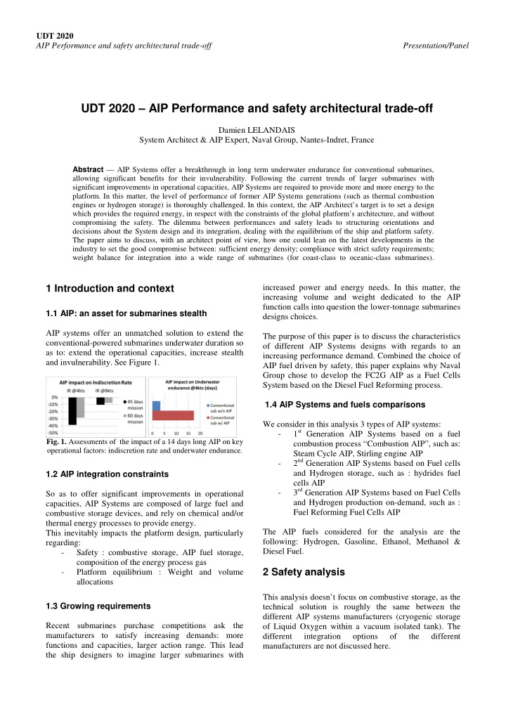
1.1 AIP: an asset for submarines stealth AIP systems offer an unmatched solution to extend the conventional-powered submarines underwater duration so as to: extend the operational capacities, increase stealth and invulnerability. See Figure 1.

  • Fig. 1. Assessments of the impact of a 14 days long AIP on key
  • perational factors: indiscretion rate and underwater endurance.

1.2 AIP integration constraints So as to offer significant improvements in operational capacities, AIP Systems are composed of large fuel and combustive storage devices, and rely on chemical and/or thermal energy processes to provide energy. This inevitably impacts the platform design, particularly regarding:

  • Safety : combustive storage, AIP fuel storage,

composition of the energy process gas

  • Platform equilibrium : Weight and volume

allocations 1.3 Growing requirements Recent submarines purchase competitions ask the manufacturers to satisfy increasing demands: more functions and capacities, larger action range. This lead the ship designers to imagine larger submarines with increased power and energy needs. In this matter, the increasing volume and weight dedicated to the AIP function calls into question the lower-tonnage submarines designs choices. The purpose of this paper is to discuss the characteristics

  • f different AIP Systems designs with regards to an

increasing performance demand. Combined the choice of AIP fuel driven by safety, this paper explains why Naval Group chose to develop the FC2G AIP as a Fuel Cells System based on the Diesel Fuel Reforming process. 1.4 AIP Systems and fuels comparisons We consider in this analysis 3 types of AIP systems:

  • 1st Generation AIP Systems based on a fuel

combustion process “Combustion AIP”, such as: Steam Cycle AIP, Stirling engine AIP

  • 2nd Generation AIP Systems based on Fuel cells

and Hydrogen storage, such as : hydrides fuel cells AIP

  • 3rd Generation AIP Systems based on Fuel Cells

and Hydrogen production on-demand, such as : Fuel Reforming Fuel Cells AIP The AIP fuels considered for the analysis are the following: Hydrogen, Gasoline, Ethanol, Methanol & Diesel Fuel.

2 Safety analysis

This analysis doesn’t focus on combustive storage, as the technical solution is roughly the same between the different AIP systems manufacturers (cryogenic storage

  • f Liquid Oxygen within a vacuum isolated tank). The

different integration

  • ptions
  • f

the different manufacturers are not discussed here.

slide-2
SLIDE 2

UDT 2020 AIP Performance and safety architectural trade-off Presentation/Panel AIP Fuel is loaded before the beginning of the mission and can hardly be cleared from the submarine in case of

  • necessity. In this matter, the AIP fuel may present a

permanent hazard to the ship and its crew. Moreover, dealing with the characteristics of the different AIP fuels (§1.4), the involvements on safety are quite different. 2.1 Fire/explosion risk assessment The chemical properties of Hydrogen (very low explosion limit and inflammation energy) lead to consider a fire and explosion risk in case of leak. Dealing with liquid fuels, the risk or explosion risk assessment can lean on their flash point [1], which characterizes the ambient temperature above which vapours emitted by a liquid fuel flake become flammable. This flash point (in °C) can be put into perspective with the European classification for fuels [2], and should be compared with the standard temperature conditions in the submarine [3] to get an opinion about the risk of fire or explosion in case of leak.

  • Fig. 2. Comparison of fuels flash points with relevant reference

temperatures Considered the data shown on Figure 2, the following summarize is considered as a global assessment of the inflammation / explosion risk: Table 1. Fire/explosion risk final assessment

Risk assessment Description Fuels LOW Fuels flammable above the Engine room ambient temperatures range Diesel Fuel MODERATE Fuels flammable above the Machinery rooms ambient temperatures range

  • HIGH

Fuels flammable within the Machinery rooms ambient temperatures range Hydrogen, Gasoline, Methanol, Ethanol

2.1.2 Toxicity risk assessment The toxicity risk in case of inhalation is considered the most critical as it potentially concerns the whole crew in case of leak. Its assessment leans on two parameters:

  • the inherent risks brought by the fuel to human

life, characterized by the fuel vaporization ability and the effects of vapours on health

  • the ease of reaching hazardous concentrations in

case of fuel leak considering the specific confined environment

  • f

a submarine, characterized by the vaporization speed and the concentration limits.

Table 2. Inherent toxicity risk assessment

Ethanol Methanol Diesel Fuel Gasoline Vaporization ability High High Limited High Hazard statements (if inhaled)

  • Cat.3 H331

(toxic)

  • Cat. 4 H332

(harmful)

  • Cat. 3 H336

(may cause drowsiness

  • r dizziness)

The analysis of the hazard statements from the GHS System [4] indicates that, dealing with the inherent risks, Ethanol and Diesel Oil imply a limited risk of toxicity. On the opposite, Methanol and Gasoline bring significantly more risks to the crew.

Table 3. Hazardous concentrations reaching assessment.

Ethanol Methanol Diesel Fuel Gasoline Vaporization speed High High Very slow High IOELV TWA / 8-hours exposure limit 1000ppm 200ppm 4300ppm 1000ppm IOELV STEL / 15-minutes exposure limit 5000ppm 1000ppm Not indicated 1500ppm

The analysis of fuels MSDS [5] show that, dealing with the reaching of hazardous concentrations onboard, the most critical fuel is Methanol, as it presents the lowest exposure limits combined with a fast vaporization of

  • liquid. On the opposite, Diesel Fuel is by far the less

critical fuel. As an overview, we can assess the toxicity risk to be the following:

  • Low

for Diesel Fuel and Ethanol

  • Moderate

for Gasoline

  • High

for Methanol 2.1.3 Global risk assessment overview Globally, the risk brought by the storage of fuel can be summarized as follow:

  • Fig. 3. AIP fuel storage permanent risk assessment overview

Machinery rooms Engine room

Standard submarine ambient temperature conditions [3] 55°C

Combustible Flammable Easily Flammable Extremely Flammable

21°C European classification for fuels [2]

10 °C 20 30 40 50 60 70

Ethanol (13°C) Gasoline (-40°C) (gaseous H2) Methanol (12°C) Diesel Fuel (>60°C)

Fuels flash points [1] 0°C

Toxicity risk Flammability/ explosion risk

LOW MODERATE HIGH LOW MODERATE HIGH

slide-3
SLIDE 3

UDT 2020 AIP Performance and safety architectural trade-off Presentation/Panel One may keep in mind that this risk is permanent as soon as the fuel has been loaded in the submarine. This explains why Diesel Fuel is the preferred fuel for Naval Group in AIP Systems in submarines.

3 Platform design analysis

The different generations of AIP Systems characteristics present significant differences in mass and volume allocations and distributions. It is interesting to look for the impact of an increasing energy demand on weight and volume assessments. In the analysis proposed hereafter, the following considerations are taken:

  • The 1st Generation AIP is a steam-cycle

combustion AIP, fed with Diesel Fuel

  • The 2nd Generation AIP is a Fuel Cells AIP, fed

with Hydrogen stored in hydrides tanks

  • The 3rd Generation AIP is a Fuel Cells AIP, fed

with Hydrogen produced on demand through a Diesel Fuel reforming process (FC2G) For all these AIP systems, the Combustive and Fuel quantities are considered proportional to the energy provided. 3.1 Mass impact So as to assess the mass impacts of the different AIP Systems, the following reactants consumption and storage efficiency figures are considered: Table 3. reactants consumption and storage efficiency figures

1st GEN AIP 2nd GEN AIP 3rd GEN AIP O2 consumption (kgO2/kWh) 1,4 0,45 0,45 < x < 1,4 O2 storage efficiency (kgO2/kg) 0,5 0,5 0,5 O2 storage mass allocation (kg/kWh) 2,8 0,9 0,9 < x < 2,8 Fuel consumption (kgFuel/kWh) 0,5 0,06 0,06 < x < 0,5 Fuel storage efficiency (kgFuel/kg) 0,9 0,0125 0,9 Fuel storage mass allocation (kg/kWh) 0,55 4,8 0,05 < x < 4,8 Fuel and O2 mass storage allocation (kg/kWh) 3,35 5,7 2,2

The Table 3 highlights the following characteristics:

  • 1st generation AIP Systems require more oxygen

than the others so as to maintain the energy production process

  • 2nd generation AIP Systems require significantly

less oxygen, but are dramatically constrained by the very low H2 storage mass efficiency

  • 3rd generation AIP Systems (FC2G) require less
  • xygen than 1st generation AIP and much less

fuel storage mass allocation than 2nd generation AIP On the overall, the mass requirements for reactants (combustive and fuel) storage are clearly different between generations:

  • Fig. 4. Comparison of mass requirements for reactants storage

between different types of AIP Systems

The Figure 4 shows that dealing with reactant storage mass balances, the integration of a 3rd Generation AIP System like FC2G is significantly easier than the other generations.

  • Fig. 5. Comparison of extra mass requirements in reply of

increasing energy demand between different types of AIP Systems

The Figure 5 estimates the reactants storage mass growth with regards to the need of extra energy. This gives the submarine designer an overview about the involvements

  • n mass balance when an increase of energy provided by

the AIP is required from an existing ship design. Note: 30MWh is the order of magnitude of the energy gap between a 2000 tons and a 3000 tons submarine It clearly points out the difficulty for the submarine designer to extend the energy provided by the AIP when using a 2nd Generation AIP without compromising the ability to fulfil all the requirements (operational, performance) coming along with the growth of the submarine.

slide-4
SLIDE 4

UDT 2020 AIP Performance and safety architectural trade-off Presentation/Panel

4 Conclusion

This study explains the major drivers of the development

  • f the FC2G AIP that Naval Group launched 15 years

ago: the use of Diesel Oil as AIP fuel, so as to offer the best safety performance for a submarine application, and the choice of a reforming process to keep reactants storage impact as low as possible and optimize its integration in the global design of the ship. The FC2G design provides today a very interesting balance between weight, performance and safety to a large range of ships, from coast-class to oceanic-class submarines.

Acknowledgements

To be completed.

References

[1] Properties of fluids in NIST web Database [2] European classification (modified 67/548/CEE and 1999/45/CE directives) [3] Bureau Veritas Naval Rules 535 Pt B, Ch 1, Sec 3, Table 3 “Air Internal environmental conditions” in Normal conditions [4] GHS system, compliant with CLP – 1272/2008 regulation [5] Fuels Master Safety Data Sheets

Author/Speaker Biographies

Damien Lelandais joined Naval Group late 2007 as Design Engineer, in charge of the development and trials

  • f AIP Energy Subsystems. This led him to get involved

in the development of the Fuel Cells AIP (FC2G) in

  • 2008. In 2012 he was appointed AIP System Architect, in

charge of the whole system, working on existing submarines as well as new designs. After diversified experiences from the feasibility phase to sea trials, he now manages the integration studies of the FC2G AIP as System Architect.