UDT 2020 Submarine power distribution by smart DC microgrid Peter - - PDF document

udt 2020 submarine power distribution by smart dc
SMART_READER_LITE
LIVE PREVIEW

UDT 2020 Submarine power distribution by smart DC microgrid Peter - - PDF document

UDT 2020 UDT Extended Abstract Template Presentation/Panel UDT 2020 Submarine power distribution by smart DC microgrid Peter Rampen MSc, Damen Shipyards, Gorinchem, Netherlands Abstract DC as an electrification platform has been


slide-1
SLIDE 1

UDT 2020 UDT Extended Abstract Template Presentation/Panel

UDT 2020 – Submarine power distribution by smart DC microgrid

Peter Rampen MSc, Damen Shipyards, Gorinchem, Netherlands

Abstract — DC as an electrification platform has been established onboard submarines since the very beginning – yet tomorrow’s DC grids will look and behave very differently from classical DC systems. In today’s DC applications, commercial projects have now implemented and demonstrated modular and scalable DC systems with fully controlled loads, sources and prosumers. However in these applications, DC is limited to a central hub, with centralized conversion and control. The market is now at a stage where the next generation of smart DC grids are soon realizable. Confidence in controlled DC systems has been established, and methodologies and components for DC integration are now accepted and proven. Together with semiconductor circuit breakers and next generation power electronic converters, a true vessel-wide DC power distribution grid is now possible and coupled with the extension of the grid as a data network, true controllability can be achieved. This enables system scalability as well as the potential for zonal distribution to be realized, allowing full controllability of loads and prosumers. Coupled with local power conversion and higher degrees of distributed control, robustness and reconfigurability are enhanced. This flexibility introduced by smart DC grids is not only operational, but also gives the designer more freedom in the choice and exploitation of novel type of power sources, like: variable or high speed generators and batteries. In this paper, the current experience and status of today’s DC systems is presented. The research topics which are being addressed in order to realise tomorrow’s generation of DC grids are then introduced, focusing especially on distributed control and the zonal architecture. This is backed up by the enabling technologies, and their state of maturity, demonstrating system safety, low-maintenance and compactness. Smart DC grids therefore make for not simply power delivery, but therefore true power distribution and control. By harnessing the benefits of smart DC, we can achieve system efficiency, and not just efficient systems.

1 Introduction

Already since the introduction of electrical power distributions in the late nineteenth century, submarines have been equipped with DC electric propulsion. The Spanish submarine Peral, commissioned in 1888, was the

  • first. This submarine would nowadays be called a full-

electric vessel – with batteries as the sole source of power, and having to be charged from an external source. When fully charged it had a maximum range of 400 nmi at 3 kts. The early DC systems used the classical “Edison DC” technology, with DC motors and generators. In the second half of the previous century, semiconductor-based solid state converter technology was introduced (see figure 1). At first only for speed control regulators on DC motors and as rectifiers for synchronous generators, nowadays PWM- based converters are widely used on board of submarines.

  • Fig. 1. Typical power configuration in the late 20th century

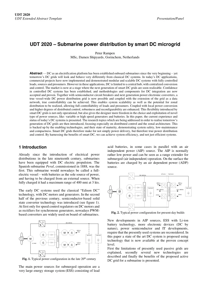
The main power sources for submerged operation are a very large energy storage system (ESS) consisting of lead acid batteries, in some cases in parallel with an air independent power (AIP) source. The AIP is normally rather low power and can be seen as a range extender for submerged (air independent) operation. On the surface the batteries are charged by an air dependent power (ADP) source.

  • Fig. 2. Typical power configuration for present-day builds

New developments in AIP sources, ESS with Li-ion battery technology, more electronic devices (DC by nature), power semiconductor and IT developments, require that the presently used systems are reconsidered. In this paper a state of the art DC system is proposed using technology that is now available at the proven concept level. First the limitations of presently used passive grids are explained, secondly several new technologies are described and finally the benefits of the proposed active DC grid for a submarine is presented.

M G G

switchboard

M G M G

lead acid lead acid 400Vac 50Hz 115Vac 400Hz 300..600Vdc 3.1 MW

M

PM

G G

propulsion switchboard 400Vac 50Hz 24Vdc main switchboard 250...600Vdc lead acid lead acid 400Vac 50Hz 24Vdc 250...600Vdc 300..600Vdc aft zone fwd zone

slide-2
SLIDE 2

UDT 2020 UDT Extended Abstract Template Presentation/Panel

2 PASSIVE DC GRID LIMITATION

For efficiency reasons the batteries are, via a short-circuit protection device, directly connected to the DC distribution system. This implies that the ESS determines the DC distribution voltage, which is depending on the ESS state of charge (SOC) and the load current. This voltage window can be up to a factor 2 (e.g. 300…600 Vdc). All equipment connected to the DC distribution therefore has to be rated for this voltage range, and as a consequence, this equipment has a current rating two times higher than that nominally required. This results in larger and heavier systems, which are key parameters for a

  • submarine. Additionally, this equipment is specially made

for this voltage range, and is therefore only affordable for the high power equipment. By numbers, most equipment is still supplied by AC and 24Vdc distribution, so large grid converters are installed to convert the main DC voltage to the auxiliary AC voltage level(s). Short-circuit protection is particularly an issue with DC due to the absence of zero crossing. Short-circuit currents in these systems are very high and steep (see figure 3), because in this low impedance system high amount of energy is stored in converter capacitors and the batteries. For short-circuit protection very large mechanical circuit breakers and special fuses are therefore needed. For today’s configurations these devices are able to switch the short-circuit currents off safely. However when new battery technologies and more capacitance is introduced these devices will be too slow to limit the high short current peaks. This can result in high arc-flash values, which can be dangerous for fire safety.

  • Fig. 3. Typical short-circuit current simulation for DC system

with high capacitance

3 Active DC grids

Several technological and social developments are driving the developments of smart DC grids. Land based power is increasingly generated by renewable energy sources, decentrally connected to the grid and which are by their very nature unpredictable sources. This requires resilient grids that are able to cope with dynamic unbalance in power demand and supply. Novel semiconductor materials like Silicon Carbide (SiC) with lower losses are now increasingly available, enabling low loss and compact solid state converters and solid state circuit breakers (SSCB). Since these devices have micro-processor based control they are by nature

  • smart. By also implementing state of the art IT systems, a

smart grid can be created. In these smart grids connected devices are remotely monitored, supervised and operated. 3.1 Solid-state circuit breakers A SSCB combines the advantage of very fast micro- processor based short-circuit detection with very fast switching characteristic of power electronic devices, as shown in figure 4. Short-circuit currents can be detected based on a high current-slope. As a result, the short circuit current can be switched-off within nominal

  • peration current, and overcurrent-rated equipment is not
  • required. For local power distribution earth fault

protection can be applied, making the system safer for personnel. Because of the fast switching time preventing high currents being reached, the short-circuit energy very low, and arc flashes will be very limited. By implementing SSCB close to equipment with large energy storage, a very safe electrical system can be created.

  • Fig. 4. MOSFET based SSCB topology

With the use of SSCBs interconnected grid topologies can be envisioned, which are reconfigurable and zonally

  • redundant. Interconnected grids increasing the optimal use
  • f the available sources.

Despite the available types being still limited, currently the first SSCB are becoming commercial available. Some types are developed for the lighting groups (about 16A), while others are available for high power 1000Vdc systems, with ratings starting at 750A up to a few kA’s. Low power SSCBs using the state of the art semiconductors, realize an advanced circuit breaker with low losses. For high current ratings, the losses are depending on the used semiconductor type. IGBT-based SSCBs are still having high losses, and need (relatively) high cooling capacity. IGCT-based SSCB on the other hand promise a lower loss circuit breaker [5], although losses are still higher than a fuse or mechanical breaker. However an SSCB has superior fault clearing and limiting characteristics compared with these devices. It is expected that SiC semiconductors are becoming available that will further improve high current SSCBs. 3.2 Partial rated DC converters Another technology that enables high efficiency integration of ESS are partial power processing converters.

micro-processor controller current

slide-3
SLIDE 3

UDT 2020 UDT Extended Abstract Template Presentation/Panel As illustrated in figure 5, a PPP converter converts only a fraction of the total power, unlike a full power processing (FPP) converter. As an example for a Li-ion battery ESS with a voltage range of 900…1100Vdc connected to a 1000Vdc grid, the PPP only has to be rated for 10% of the total power. For connecting devices with a small voltage range, like batteries, the PPP converter is compared to a FPP converter much smaller and more efficient [4].

  • Fig. 5. Principle of a PPP compared to a FPP [4]

This kind of converters are for now only proven in laboratory and are not commercial available yet. 3.3 High-frequency DC transformers The volume of electromagnetic components like coils and transformers is inversely proportional with the frequency (see figure 6). Consequently, DC/DC converters using a high frequency link with an internal transformer, enable the existence of DC transformers that are compact, efficient and additionally have galvanic isolation between input and output.

  • Fig. 6. Size comparison for high frequency and low frequency

transformer [7]

3.4 Hierarchical power control Advanced control and coordination concepts have been developed for micro grids using a hierarchical control scheme [1]. As illustrated in figure 7 this power control has the following levels

  • Level 0. Fundamental control loops to regulate

voltage and current of each connected device.

  • Level 1. Primary control loop, making the system

dynamically stable, using voltage droop at device level for load sharing, and load shedding

  • Level 2. Secondary control (distributed at zone

level), quasi-static power demand balancing, power generation and energy storage.

  • Level 3. Tertiary control. Optimize power system for

a certain operational goal (e.g. energy efficiency, performance or maintenance cost. In commercial hybrid ships these kind of control schemes are already applied and proven.

  • Fig. 6. Different levels in hierarchical power control

4 Proposed configuration

The technical innovations described in the previous chapters, are enabling new topologies for future

  • submarines. A conceptual example of this is shown in

figure 7.

  • Fig. 7. Proposed topology for submarine application

This concept uses:

  • Zonal ring topology, in order that there are two

power routes available and zones are equal to the submarine safety zones

  • SSCB realizing very fast isolation of short circuits
  • Distributed ESS and generators, enabling a high

redundancy

  • ESS connected with PPP converter, enabling a high

efficiency connection to the fixed voltage grid

physical layer 2nd layer secondary control 1st layer primary control 3rd layer tertiary control electrical network: V

engine

G

speed control

Battery pack

BMS volt. contr.

M Power Management System (PMS) Propulsion control system (PCS)

speed contr.

Energy Management System (EMS)

sub- grid volt contr. volt contr.

M

PM

G

ADP SSCB SSCB SSCB SSCB SSCB SSCB SSCB SSCB zone 2 auxiliaries SSCB SSCB zone 1 auxiliaries SSCB SSCB zone 3 auxiliaries ESS ESS

G

AIP SSCB SSCB SSCB SSCB ESS SSCB SSCB SSCB ESS SSCB

slide-4
SLIDE 4

UDT 2020 UDT Extended Abstract Template Presentation/Panel

  • Fixed voltage system, making optimal use of

converter ratings

  • Local distribution for small consumers, redundantly

supplied by galvanically insulated converters

  • Hierarchical control, making a robust control system,

while also using the full system capability

5 Trade-off review

High availability of power across the submarine is guaranteed by using the ring topology, distributed ESS, distributed power control and very fast short circuit protection. The fast short-circuit protection and extra safe separate distribution for smaller consumers creates a system with a very low probability of fire and extremely low arc-flash values. Since the switching of a SSCB can not be disturbed by mechanical shock and vibrations, it will be more easy to comply with the high submarine regulatory test requirements for shock and vibrations. The proposed system uses converters and SSCB which have much smaller dimensions then nowadays used

  • components. Furthermore the system power losses will be

lower as well, requiring a smaller cooling systems. By using the smart control and the interconnected grid, all sources are automatically used optimally, such that possibly smaller generators and ESS can be installed.

6 Conclusions

Using smart DC microgrid technology will make power systems for submarines more optimal, safer and more

  • compact. Most of the innovations proposed in this paper

are still at a relatively low technology readiness level. Such a power system cannot be fully realised today. Nevertheless some of these innovations are currently available with some limiting capability, and others can be scaled to industrial readiness levels with some effort. With the right motivation, smart DC microgrids using the presented technologies can be applied on submarines within the development time of a submarine.

Acknowledgements

The author would like to acknowledge the support and good cooperation of:

  • Anders Wikström and Johan Gunnarsson of Saab

Kockums for helping on the submarine application case and reviewing the paper

  • Edward Sciberras of Damen Shipyards for reviewing

the proposed technology and paper

References

[1] Z. Jin, G. Sulligoi, R. Cuzner, L. Meng, J. C. Vasquez and J. M. Guerrero, Next-Generation Shipboard DC Power System: Introduction Smart Grid and dc Microgrid Technologies into Maritime Electrical Networks,in IEEE Electrification Magazine, vol. 4,

  • no. 2, pp. 45-57, June 2016.

[2] L. Mackay, N. van der Blij, L. Ramirez Elizondo, P. Bauer, Toward the Universal DC Distribution System, Electric Power Components and Systems, 45:10, 1032-1042, DOI: 10.1080/15325008.2017.1318977 [3] P. Rampen, C. Meijer, H. Stokman, Next generation hybrid power system: Enhanced safety and performance by fully controlled smart DC, Imarest MECSS 2015 [4] J. Rojas, H. Renaudineau, S. Kouro, S. Rivera, Partial Power DC-DC Converter for Electric Vehicle Fast Charging Stations [5] L. Qi, P. Cairoli, Z. Pan, C. Tschida, Z. Wang, V. Ramanan, L. Raciti, A. Antoniazzi, Solid-State Circuit Breaker Protection for DC Shipboard Power Systems: Breaker Design, Protection Scheme, Validation Testing, IEEE Transactions on Industry Applications ( Early Access ) 2019 [6] W. Kong, Review of DC Circuit Breakers for Submarine Applications, Maritime Platforms Division, DSTO, Australia 2012 [7] R. Raju, R. Steigerwald, M. Dame, P. Cioffi, M. Schutten, L. Garces, J. Dai, R. Zhou, High voltage, high frequency silicon carbide power electronic building blocks, Imarest EAAW 2015 [8] P. Bauer, TU Delft roadmap to DC, DC Summit, Delft 2020

Author/Speaker Biographies

Peter Rampen, MSc graduated in Electrical Engineering at the Delft University of Technology, at the Electrical Power Processing department. He has been a Technical Consultant in the field of Electrical Power Generation and Distribution and Drives. He is now working as a principal research engineer in the discipline of ship’s electrics & automation at the Damen R&D department. In the last decade Peter has been involved in the developments of DC distributions systems in sustainable ship applications.