
SLIDE 1
1
Turning and Related Operations Turning is widely used for machining - - PowerPoint PPT Presentation
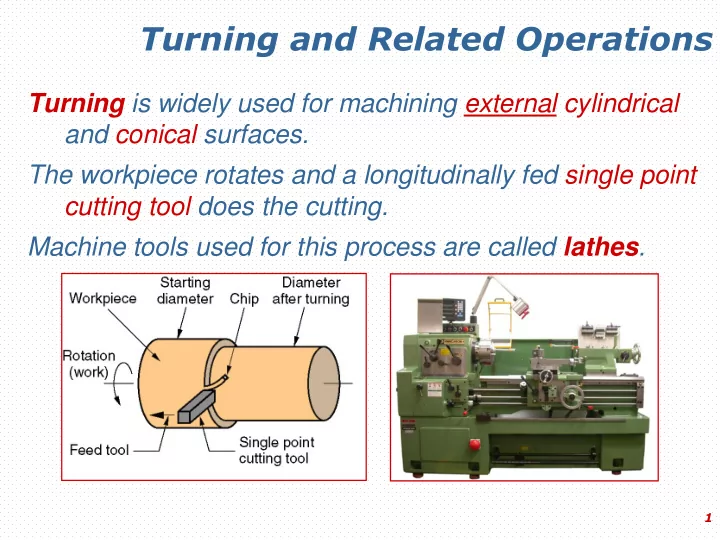
Turning and Related Operations Turning is widely used for machining external cylindrical and conical surfaces. The workpiece rotates and a longitudinally fed single point cutting tool does the cutting. Machine tools used for this process are
1
2
3
4
5
6
7
8
9
ISO Metric thread
10
11
12
13
14
15
16
17
Lead screw Feed rod Spindle direction selector lever and rod
18
19
20
21
22
23
A giant horizonal lathe (Bilim Makina A. Ş.-BURSA)
24
25
26
27
28
29
30
31
32
Tools are on a tool head.
33
34
35
36
37
38
39
40
41
42
43
Fixture Workpiece
44
45
46