
SLIDE 1
Transient response of RC and RL circuits
ENGR 40M lecture notes — July 26, 2017 Chuan-Zheng Lee, Stanford University Resistor–capacitor (RC) and resistor–inductor (RL) circuits are the two types of first-order circuits: circuits either one capacitor or one inductor. In many applications, these circuits respond to a sudden change in an input: for example, a switch opening or closing, or a digital input switching from low to high. Just after the change, the capacitor or inductor takes some time to charge or discharge, and eventually settles on its new steady state. We call the response of a circuit immediately after a sudden change the transient response, in contrast to the steady state.
A first example
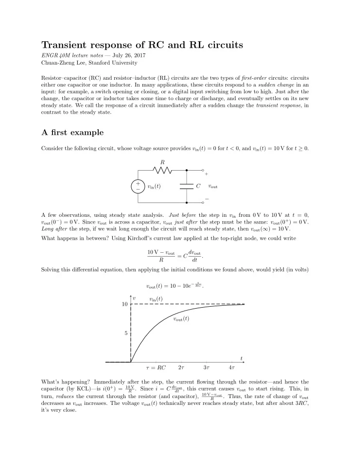
Consider the following circuit, whose voltage source provides vin(t) = 0 for t < 0, and vin(t) = 10 V for t ≥ 0. − + vin(t) R C
+
− vout A few observations, using steady state analysis. Just before the step in vin from 0 V to 10 V at t = 0, vout(0−) = 0 V. Since vout is across a capacitor, vout just after the step must be the same: vout(0+) = 0 V. Long after the step, if we wait long enough the circuit will reach steady state, then vout(∞) = 10 V. What happens in between? Using Kirchoff’s current law applied at the top-right node, we could write 10 V − vout R = C dvout dt . Solving this differential equation, then applying the initial conditions we found above, would yield (in volts) vout(t) = 10 − 10e−
t RC .
τ = RC 2τ 3τ 4τ 5 10 vout(t) vin(t) t v What’s happening? Immediately after the step, the current flowing through the resistor—and hence the capacitor (by KCL)—is i(0+) = 10 V
R . Since i = C dvout dt , this current causes vout to start rising. This, in
turn, reduces the current through the resistor (and capacitor), 10 V−vout
R