SLIDE 22 High Voltage Winding Failures from Switching
By Philip J Hopkinson, PE
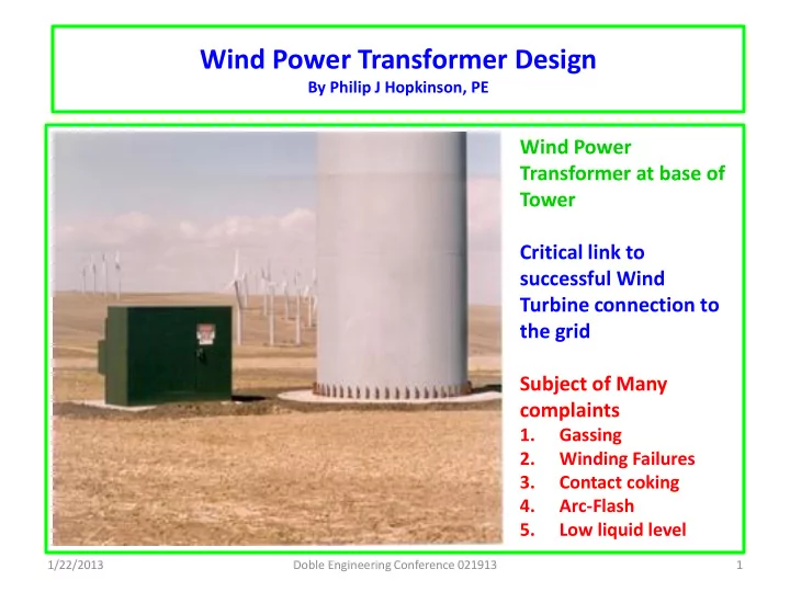
1/22/2013 22
Ping test #5 at Tap 4-5 & 9.5 amps Feb. 1. 06 Island Park Substation Unit #2 Line 1 to Gr. Voltage With 20:1 Attenuators & Arc Gap@ 5.5"
20 40 60
200 400 600 800 1000 Microseconds kV
contacts open and transient recovery voltage (TRV) rises by Ldi/dt to (-)100
kV in~90 µsec.
- 2. Contacts reignite back into
conduction, current rises to peak and decays to chopping level, inducing oscillatory
- transient. Voltage rises by
+145 kV in <1 µsec., then
- scillates to zero.
- 3. Current decays and is chopped out
- f conduction and voltage oscillates to
zero.
sufficiently to prevent reignition current and interruption is completed
voltage rises to (-)80
kV, then breaker
reignites, raising voltage by +120 kV in <1 µsec., etc.
Load-break Switching
Current chopping unavoidable at light currents < 6 amps Reignition transients likely at low power factor Circuit damping key to solving problems
The higher the system energy efficiency the more likely are winding failures
Doble Engineering Conference 021913