
SLIDE 1
1
- Prof. S. Ben-Yaakov , DC-DC Converters
[3- 1]
Magnetics Design
3.1 Important magnetic equations 3.2 Magnetic losses 3.3 Transformer 3.3.1 Ideal transformer (voltages and currents) 3.3.2 Equivalent circuit of transformer (coupling, magnetization current) 3.3.3 Design of transformer 3.4 Inductor design
- Prof. S. Ben-Yaakov , DC-DC Converters
[3- 2]
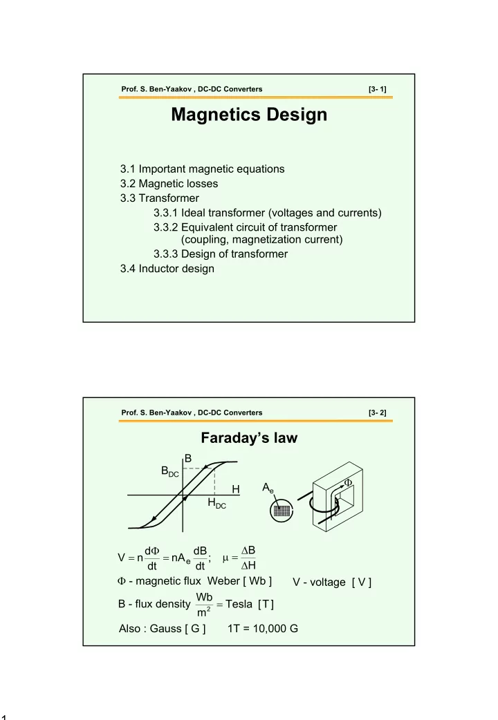
; dt dB nA dt d n V
e
= Φ = H B ∆ ∆ = µ Φ - magnetic flux Weber [ Wb ] B - flux density ] T [ Tesla m Wb
2 =