
SLIDE 1
1
Mor M. Peretz, Switch-Mode Power Supplies
[3-1]
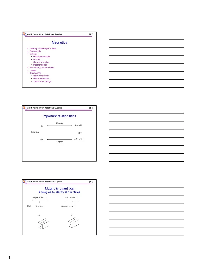
Magnetics
- Faraday’s and Amper’s laws
- Permeability
- Inductor
- Reluctance model
- Air gap
- Current crowding
- Inductor design
- Skin effect, proximity effect
- Losses
- Transformer
- Ideal transformer
- Real transformer
- Transformer design
Mor M. Peretz, Switch-Mode Power Supplies
[3-2]
Important relationships
v t
- ,
B t t , H t F t i t Faraday Ampere Core Electrical Mor M. Peretz, Switch-Mode Power Supplies [3-3]
Magnetic quantities
Analogies to electrical quantities
- ,
B
- M
F H Magnetic field H
- Electric field E
- V
E , J I
- B