Ther ermal mal Simu mulation lation of IGB GBTs s Use sed d - - PowerPoint PPT Presentation

ther ermal mal simu mulation lation of igb gbts s use sed
SMART_READER_LITE
LIVE PREVIEW

Ther ermal mal Simu mulation lation of IGB GBTs s Use sed d - - PowerPoint PPT Presentation

Ther ermal mal Simu mulation lation of IGB GBTs s Use sed d in Hybrid rid- Ruben Bons El Elect ectric ric Veh ehicles cles Electronics Sector Manager CD-adapco ruben.bons@cd-adapco.com Power er Del eliv iver ery y in in


slide-1
SLIDE 1

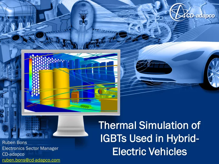
Ther ermal mal Simu mulation lation of IGB GBTs s Use sed d in Hybrid rid- El Elect ectric ric Veh ehicles cles

Ruben Bons Electronics Sector Manager CD-adapco ruben.bons@cd-adapco.com

slide-2
SLIDE 2

Power er Del eliv iver ery y in in HEVs

Batteries eries El Electr tric c Mot

  • tor
  • rs

Power r El Electr tronic

  • nics
slide-3
SLIDE 3

IGBT T = Insulat sulated d gate e bipolar

  • lar transi

nsist stor

  • r

Wiki kiped pedia: a:

– “…primarily used as an electronic switch…” – “…is noted for combining high efficiency and fast switching.” – “Availability of affordable, reliable IGBTs is an important enabler for electric vehicles and hybrid cars.”

IGBT Backgr ground

slide-4
SLIDE 4

IGBTs s can often en show >95% 5% efficiency iciency 𝜽 = thermal losses electrical power transmitted IGBTs s can transmit nsmit 20 kW, , 50 kW, , or more re electric ctrical al power

– Thermal losses can be >1 kW!

Types es of losses ses

– Conductive – Switching

Ther erma mal l Losses es in in IGBTs

IGBT T packages ges typica cally lly include de an integra egrated d diode

  • de as well

ll The e over erall all package ge often en has s mul ultip iple le IGBT/d /diode iode set ets

slide-5
SLIDE 5

Physical sical IGBT structu ucture

slide-6
SLIDE 6

Physical sical IGBT Structu ucture

slide-7
SLIDE 7

Advant ntages ges Disadv dvant ntages ges

Det etail iled ed as assem embly bly

  • Get full geometric temperature

distribution

  • Identify specific hotspots
  • Well-suited for transient
  • Longer setup time
  • Higher computational cost
  • High geometric aspect ratio,

so not favorable for large assemblies

Simpl implif ifie ied d assem embly bly

  • Provides geometry for visual

results viewing

  • Well-suited for inclusion in a

larger assembly

  • Not suitable for transient
  • Limited temperature

distribution details

  • Need extra calculation to get

junction temperature

RC net etwor

  • rk
  • Most computationally efficient
  • Inherently suitable for

transient

  • Directly utilizes vendor data

(assumed accurate)

  • No geometric equivalence

(abstraction)

  • Requires Java scripting to

implement in STAR-CCM+

  • No visual temperature plot

for the IGBT

Ther erma mal l Mode delin ing g App pproache aches

slide-8
SLIDE 8

Det etail iled ed Assem embly bly (en encaps psul ulant nt hid idde den)

slide-9
SLIDE 9

Simpl implif ifie ied d Assem embly bly (encaps psul ulant nt hid idde den)

slide-10
SLIDE 10

The e power assigne ned d to the e block

  • ck shou
  • uld

ld be the e sum um of the e conduc nducti tion

  • n &

switchi tching ng losses ses for all the e IGBT T & diode

  • de pads (= Ptot
  • tal

al).

). To com

  • mpute

e the e jun unct ction ion tem emperat perature ure Tj:

– Measure the temperature at one or more points on the copper base plate – Calculate

Tj = Tbase + [ Rth(j-c)*Ptotal ]

Simpl implif ifie ied d Assembl embly y Mode del in in STAR-CC CCM+: +: Tjun

uncti ction

  • n calcula

culati tion

  • n
slide-11
SLIDE 11

RC Net etwor

  • rk
slide-12
SLIDE 12

Because ause IGBTs s are bui uilt t for switch ching ing applicat ations, ions, we e need eed to conside nsider if therm ermal l transients nsients are imp mpor

  • rta

tant nt Do this by com

  • mparing

ring the e electr ectrica ical l time me scale e to the e therma ermal l time me scale. e.

Transie ient Consid ider eration ations