
SLIDE 1
Subsea Deployment Systems Ltd.
The SDS Skip Subsea Deployment Systems Ltd. Subsea Deployment - - PowerPoint PPT Presentation
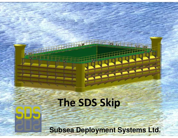
The SDS Skip Subsea Deployment Systems Ltd. Subsea Deployment Systems Ltd. SUBSEA SKIP An alternative to enhance the recovery of structures, spool pieces, mattresses etc. during decommissioning work Can be used to transport complex
Subsea Deployment Systems Ltd.
Subsea Deployment Systems Ltd.
2
SUBSEA SKIP
pieces, mattresses etc. during decommissioning work
field for installation by another vessel
Subsea Deployment Systems Ltd.
3
The SKIP consists of UPPER SEALED TUBULARS designed to required water depth (typ. 150m). The amount of buoyancy is sufficient to render the SKIP slightly positively buoyant when without payload and the lower tubular fully flooded
SKIP
Subsea Deployment Systems Ltd.
4
The SKIP consists of LOW ER FLOODABLE TUBULARS which have ballasting
carrying capacity of the SKIP . The empty SKIP will be fully ballasted during the submerged tow and all valves will remain open to the sea to avoid hydrostatic collapse
SKIP
Subsea Deployment Systems Ltd.
5
The CASTLES are positioned above the majority of the upper tubulars and protrude above the waterline in the deep draught condition allowing fine tuning of the trim
SKIP
Subsea Deployment Systems Ltd.
6
The SI DE AND DOUBLE BOTTOM TANKS will contain ‘permanent’ water ballast and will be left open to sea at points above their upper boundary to ensure they do not contribute to free surface effects when submerging or surfacing the SKIP . They will have ballasting facilities
SKIP
Subsea Deployment Systems Ltd.
7
The HOLD is completely water tight and allows the SKIP to be brought to shallow
high and ensuring a positive separation between the Centre of Buoyancy (CoB) and the Centre of Gravity (CoG) at all times
SKIP
Subsea Deployment Systems Ltd.
8
The CONTROL CHAI NS are lowered into chain CONTROL TOW ERS to control the SKIP during set-down and recovery. The weight of the chain supported by the SKIP at the base of the chain towers is used to control the height of the SKIP . The length (weight) of chain suspended within the chain towers provides lateral and rotational control of the SKIP
SKIP
Subsea Deployment Systems Ltd.
9
The TOW CHAI N CLUMP W EI GHT is inserted into the tow rigging to provide the necessary weight to submerge the SKIP from the deep draught tow condition to the submerged tow condition. It also acts as an anchor for the SKIP when parked above the seabed
SKIP
Subsea Deployment Systems Ltd.
10
Subsea Deployment Systems Ltd.
11
CONTROL CHAIN TOWERS & DYNAMICS
Control Chain / Towers
Dynamics
20% of Surface Vessel
Subsea Deployment Systems Ltd.
12
SKIP
32m
16m
8m
300Te
300Te
* May be deeper if upper tubular pressurised
Subsea Deployment Systems Ltd.
13
SKIP BASICS
maximum water depth
to the sea
pods) to control the de‐ballasting function of the hold
pressurised air in the lower tubular compartments
Subsea Deployment Systems Ltd.
14
SKIP SEABED OPERATIONS
the skip)
and gabions may be placed in steel wire cargo nets before being landed into the skip
Subsea Deployment Systems Ltd.
15
MATTRESSES
speed loaders)
areas within the skip
hold) (same rigging / cargo nets would be used
for offloading onshore)
Subsea Deployment Systems Ltd.
16
DE‐BALLASTING THE SKIP
ballast weight is used
(Note: The pressure in the lower tubulars will later be used to de‐ballast water in the main hold)
Subsea Deployment Systems Ltd.
17
SKIP RECOVERY
ballasting
seabed
submerged tow
Subsea Deployment Systems Ltd.
18
SURFACING OF THE SKIP
however, it may be done offshore if weather permits
payload during the surface tow
weather minimising roll and pitch
Subsea Deployment Systems Ltd.
19
SURFACING INTEGRAL SKIP
Upper tubular
(fully sealed, buoyancy equals submerged weight
Lower tubular
(c/w ballasting facilities)
Side and Double Bottom Tanks
(high point open to the sea)
Hold
(water can be pumped out of the hold using pressurised air from lower tubular)
Remotely operated
(Valves will be operated remotely for de‐ballasting)
Subsea Deployment Systems Ltd.
20
SURFACING OF THE SKIP
to dead slow ahead
chain clump weight to bring the skip to surface
the chain clump weight
Subsea Deployment Systems Ltd.
21
SURFACING OF THE SKIP
upper tubular members breaking the surface due to the excess buoyancy
‘hatch coaming’ above tubular is allowed to escape to match the
Subsea Deployment Systems Ltd.
22
SURFACING OF THE SKIP
water pumps will be activated to expel the remaining water in the hold
driven by the energy stored in the lower tubular
Subsea Deployment Systems Ltd.
23
SURFACING OF THE SKIP
completely emptied of water within the hold
throughout, ‘permanent’ water ballast will be kept in the side and double bottom tanks
Subsea Deployment Systems Ltd.
24
SKIP STABILITY
between CoG and CoB when submerged
that hull free surface effects during ballasting
instability during surface
Subsea Deployment Systems Ltd.
25
TOW FORCES
(Note: If conditions are benign then surface tow will be faster)
Subsea Deployment Systems Ltd.
26
Lerwick 95nm Nigg 210nm Burntisland 270nm
SOME DEMOB LOCATIONS
Bergen 130nm Haugesund 110nm Stavanger 135nm
Subsea Deployment Systems Ltd.
27
SCHEDULE
Subsea Deployment Systems Ltd.
28
CAPEX / OPEX
downtime (can be significant when avoiding to recover to deck)
Subsea Deployment Systems Ltd.
29
SAFETY AND ENVIRONMENT
deck
Subsea Deployment Systems Ltd.