THE EFFECT OF PROCESSING PARAMETERS ON STRUCTURAL PROPERTY FOR - - PDF document

the effect of processing parameters on structural
SMART_READER_LITE
LIVE PREVIEW

THE EFFECT OF PROCESSING PARAMETERS ON STRUCTURAL PROPERTY FOR - - PDF document

18 TH INTERNATIONAL CONFERENCE ON COMPOSITE MATERIALS THE EFFECT OF PROCESSING PARAMETERS ON STRUCTURAL PROPERTY FOR FILAMENT-WOUND COMPOSITE PRESSURE VESSELS T.Lili 1* , Z.Limin 2 , W. Zhenqing 1 1College of Aerospace and Civil Engineering


slide-1
SLIDE 1

18TH INTERNATIONAL CONFERENCE ON COMPOSITE MATERIALS

1 Introduction Filament winding is a popular production technique for composite structures. Cylinder pressure vessel with elliptical dome is an efficient product which can make full use of tensile strength of fiber. To achieve the most efficient use of the reinforcement material the fiber should be placed in the maximum load directions or in geodesic path. This is not always achievable as the fibers must not slip during the winding process due to windability. Windability means fiber bands should cover uniformly on the mandrel without voids or significant overlap toward radial and circumferential directions. Realistic pattern information is very important for an optimal design because it is directly related with the accuracy if finite element analyses.

F.H.Abdalla9[1] design a lathe-type machine for low cost filament winding process. Haisheng Li[2] presents a new class of trajectories with more freedom by generalizing spline and give the conditions to make these splines on cylinders and cones stable. Cheol[4] use semi- geodesic path algorithm to calculate possible winding patterns taking into account the windability and slippage between the fiber and the mandrel surface. D.T.Jones[5] describes delta-axisymmetric methods that result in a constant thickness lay-up of composite over the end closures of a dome-end cylindrical vessel. Tae-kyung[6] verified the size effect on the fiber strength of a composite pressure vessel but didn’t mention the winding pattern. In this paper, the practical process parameters which areis important for design are studied and two methods for calculating mandrel rotated angle are discussed.

2 Theory for filament winding trajectories 2.1 Plane-hypothesis theory

This is a simplified method that supposes the fiber path at dome lies in a plane. It is easy to calculate the mandrel rotating angle at dome as following: ⎟ ⎠ ⎞ ⎜ ⎝ ⎛ − + =

D d htgα θ 2 sin 90 2

1 1

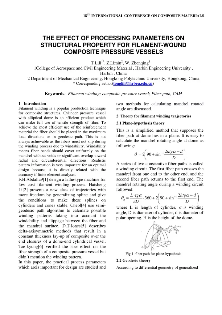
A series of two consecutive fiber paths is called a winding circuit. The first fiber path crosses the mandrel from one end to the other end, and the second fiber path returns to the first end. The mandrel rotating angle during a winding circuit followed: ⎟ ⎠ ⎞ ⎜ ⎝ ⎛ − + + ⋅ ⋅ =

D d htg D tg L

n

α π α θ 2 sin 90 2 360

1

where L is length of cylinder, α is winding angle, D is diameter of cylinder, d is diameter of polar opening. H is the height of the dome.

Fig.1 fiber path for plane-hypothesis

2.2 Geodesic theory According to differential geometry of generalized

THE EFFECT OF PROCESSING PARAMETERS ON STRUCTURAL PROPERTY FOR FILAMENT-WOUND COMPOSITE PRESSURE VESSELS

T.Lili1*, Z.Limin2, W. Zhenqing1 1College of Aerospace and Civil Engineering Material , Harbin Engineering University , Harbin , China 2 Department of Mechanical Engineering, Hongkong Polytechnic University, Hongkong, China

* Corresponding author(tonglili@hrbeu.edu.cn)

Keywords: Filament winding; composite pressure vessel; Fiber path, CAM

slide-2
SLIDE 2

Fig.2. parameter figure for ellipse equation

spaces, a regular three-dimensional surface can be described as a vector function of two independent parameters:

( ) ( ) ( ) ( ) { }

φ θ φ θ φ θ φ θ , , , , , , z y x S = with ℜ ∈ φ θ,

For ellipsoid shape of mandrel dome, its surface can be described as following:

{ }

u a v u b v u b r sin , sin cos , cos cos =

Coefficients of the first fundamental form are equal to: u a u b v z v y v x E

2 2 2 2 2 2 2

cos sin + = ⎟ ⎠ ⎞ ⎜ ⎝ ⎛ ∂ ∂ + ⎟ ⎠ ⎞ ⎜ ⎝ ⎛ ∂ ∂ + ⎟ ⎠ ⎞ ⎜ ⎝ ⎛ ∂ ∂ =

= ∂ ∂ ⋅ ∂ ∂ + ∂ ∂ ⋅ ∂ ∂ + ∂ ∂ ⋅ ∂ ∂ = v z u z v y u y v x u x F u b u z u y u x G

2 2 2 2 2

cos = ⎟ ⎠ ⎞ ⎜ ⎝ ⎛ ∂ ∂ + ⎟ ⎠ ⎞ ⎜ ⎝ ⎛ ∂ ∂ + ⎟ ⎠ ⎞ ⎜ ⎝ ⎛ ∂ ∂ = Differential equation of geodesic line at revolutionary curved surface is: τ τ τ tg tgu tg u nG v nE G E u ⋅ = ∂ ∂ − ∂ ∂ = ∂ ∂ 2 1

τ τ tg u u k u tg G E u v cos cos sin

2 2

+ = = ∂ ∂

(2) Where τ is winding angle and v is mandrel rotating angle.

  • 3. Windability and practical wind pattern

As mentioned above, windability is very important because some of the patterns calculated by Eq.(1) and Eq.(2) may be useless for the manufacture of filament wound structures unless uniform coverage is considered. If the number of fiber bands in a layer is N and the circumferential shifted integer is K, the relationship of K and N should be relative prime in order to satisfy the windability. Practical mandrel rotating angle is equal to:

360 cos 360 ⋅ + ⋅ = α π θ D N b N K

n

(3) Where b is width of fiber band. Data for relationship between mandrel rotating angle and number of fiber bands showed in table-1.

Table-1 relationship between mandrel rotating angle and number of fiber bands

bands Patten K/N Angle ° Patten K/N Angle ° Patten K/N Angle ° 1 1/1 360 2/1 720 3/1 1080 2 1/2 180 3/2 540 5/2 900 1/3 120 4/3 480 7/3 840 3 2/3 240 5/3 600 8/3 960 1/4 90 5/4 450 9/4 810 4 3/4 270 7/4 630 11/4 990 1/5 72 6/5 432 11/5 792 2/5 144 7/5 504 12/5 864 3/5 216 8/5 576 13/5 936 5 4/5 288 9/5 648 14/5 1008 1/6 60 7/6 420 13/6 780 6 5/6 300 11/6 660 17/6 1020

Winding pattern for different number of fiber bands is showed in fig.-3.

(1) N=3 (2) N=4 (3) N=5 (4)N=6

Fig.-3 Winding pattern for different number of fiber bands

According to equation (1) or (2), mandrel rotating angle can be calculated. The nearest winding pattern can be found in table-1. spatial trajectories was adjusted slightly to be identical with the practical winding pattern. The following winding angle at dome of arbitrary position can be obtained: ( ) ( ) ( )

2 1 2 2 1 2 2 1 2

360 arcsin z z y y x x D − + − + − ⋅ Δ = π θ α

(4) Thickness at dome is equal to:

slide-3
SLIDE 3

3 PAPER TITLE

α

α α

f f

t d D t cos cos = (5) Where d is diameter at dome of arbitrary position,

α f

t is thickness of cylinder.

  • 4. Result and discussion

The performance of composite structures completely depends on the distribution of the fiber, which is determined by the filament winding pattern. 3-D spatial data of the winding trajectories were simulated by using C++ programming language. The parameters were showed in fig.4.

Fig.-4 Winding trajectories simulation

For example, L=410mm, D=146mm, h=40mm, d=31.5mm, p=0.55. mandrel winding angle according to equation(1) is 502°,504°should be chosen according to table-1. It is 442.7° according to equation(2) and 450°is the nearest angle for windability. 442.7°is the most stable pattern at dome due to it is geodesic line and 450°is the nearest angle to geodesic trajectories meanwhile it keeps to

  • windability. Comparatively, the winding pattern

according to plane-hypothesis is farther to the geodesic line and unstable though it is applied widely because it is simple and easy to be used. The thickness was calculated according to equation (5). The results showed that nearly no difference between the result of two method. However, this was not the real truth because the fiber would slide toward stable trajectories when it was far from the geodesic line. The result was that the thickness near polar hole was bigger than anticipated due to the bigger mandrel rotating angle.

Fig.-5 Winding angle for different methods 15 30 45 60 75 90 15 25 35 45 55 65 75 r(mm) winding angle at dome quati-geodesic method-450 geodesic line-443 plane-hypothesis method-504

The thickness was related with the friction coefficient between fiber band and mandrel. Therefore, the fiber path should be close to the geodesic line to avoid fiber stack and sliding. The result for different parameters showed in Fig.-7. For L=500mm,p=0.5,radius of cylinder R and radius of polar opening r0 is variable. The result showed that the mandrel winding angle decreased as radius of cylinder increase and radius of polar opening decrease. The difference between result of two methods increases as r0 increase, but it is nearly constant when R increased.

  • 5. Conclusion

In this research, winding patterns considering windability were presented. Two methods for calculating mandrel rotating angle were

  • discussed. Plane-hypothesis method gave the

unstable winding trajectories far from the geodesic line and result in fiber stack especially

Fig.-7 mandrel rotating angle at different parameters

600 1200 1800 2400 3000 0.2 0.4 0.6 0.8 1

R/L mandrel rotating angle

method1-ro/R=0.1 method2-ro/R=0.1 method1-ro/R=0.5 method2-ro/R=0.5 method1-ro/R=0.9 method2-ro/R=0.9

slide-4
SLIDE 4

when radius of polar opening increased. The angle at dome have no obvious difference with two methods but the thickness calculated by plane-hypothesis near polar opening increased due to unstable path and fiber stack. Plane- hypothesis method was suggested not to be applied during fiber winding process though it is simple and easy to be used.

References [1] F.H.Abdalla, S.A.Mutasher. Design and fabrication of low cost filament winding machine. Materials &Design, 2007, 28:234-239. [2] Haisheng Li, Youdong Liang. Splines in the parameter domain of surfaces and their application in filament winding.Computer-aided Design. 2007,39:268-275

[3] L.L.Tong, Z.Q.Wang. Progressive Failure Analysis of Composite Pressure Vessels by Finite Element Method. Key Engineering Materials.2007,348:133-136

[4] Cheol-Ung Kim, Ji-Ho Kang. Optimal design of filament wound structures under internal pressure based on the semi-geodesic path algorithm. Composite Structures. 2005,67:443-452 [5] D.T.Jones, I.A.Jones. Improving composite lay- up for non-spherical filament-wound pressure

  • vessels. Composites:Part A. 1996,27A:311-317

[6] Tae-Kyung Hyung, Chang-Sun Hong. Size effect

  • n the fiber strength of composite pressure vessels.

Composite Structures. 2003,59:489-498