
SLIDE 1
Technical Report 4
Macenzie Ceglar Structural Option Advisor: Heather Sustersic Lateral System Analysis
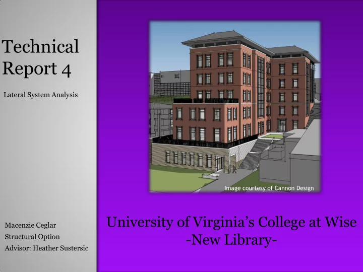
University of Virginia’s College at Wise
- New Library-
Image courtesy of Cannon Design
Technical Report 4 Lateral System Analysis Image courtesy of - - PowerPoint PPT Presentation
Technical Report 4 Lateral System Analysis Image courtesy of Cannon Design University of Virginias College at Wise Macenzie Ceglar -New Library- Structural Option Advisor: Heather Sustersic Shear Walls Foundation Walls Shear Walls
Macenzie Ceglar Structural Option Advisor: Heather Sustersic Lateral System Analysis
Image courtesy of Cannon Design
Shear Walls Foundation Walls
Shear Walls
ASCE7-05 requires four different wind loading conditions be applied in order to account for quartering winds and torsion. Pressures were calculated for these four cases and applied as forces each story level using tributary area in order to transfer the load through the diaphragm to lateral elements.
Vertical Applied at each story level Horizontal Applied at center of pressure
Vertical Applied at each story level Horizontal Applied at center of mass
ASCE7-05 requires that accidental torsion be considered for both orthogonal directions, and orthogonal interaction effects are permitted to be neglected base on the seismic category B. Forces along with moments due to torsion were applied at each story level in order to transfer the load through the diaphragm to lateral elements.
Max Soil Depth: 60 FT Equivalent Lateral Fluid Pressure:
Vertical Applied at each story level
Horizontal Applied at center of each
The equivalent lateral fluid pressure was converted into multiple point loads at each level based on tributary area and soil depth. Forces were applied at each story level in order to transfer the load through the diaphragm to lateral elements.
Wall thickness at base: 33” Loading Condition: Soil Loads in the x-direction Maximum Moment: 65,214 K-FT
Wall thickness at base: 12” Loading Condition: Soil Loads in the x-direction Maximum Moment: 51,194 K-FT
Shear Wall 2
Shear Wall 6
Wall thickness at base: 12” All other wall thicknesses: 12”
Strength Drift – Wind Drift – Seismic Overturning Moment