
SLIDE 1
1
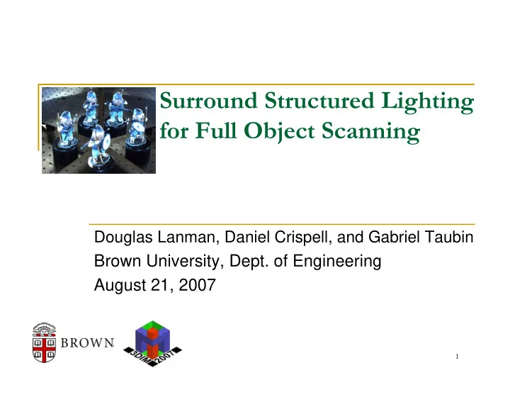
Surround Structured Lighting for Full Object Scanning Douglas - - PowerPoint PPT Presentation
Surround Structured Lighting for Full Object Scanning Douglas Lanman, Daniel Crispell, and Gabriel Taubin Brown University, Dept. of Engineering August 21, 2007 1 Outline Introduction and Related Work System Design and Construction
1
Surround Structured Lighting 2
Surround Structured Lighting 3
References: [8,9]
projecting a temporally-multiplexed binary image sequence
Point Grey Flea2
(15 Hz @ 1024 x 768)
Mitsubishi XD300U
(50-85 Hz @ 1024 x 768)
Surround Structured Lighting 4
References: [8,9]
projecting a temporally-multiplexed binary image sequence
Point Grey Flea2
(15 Hz @ 1024 x 768)
Mitsubishi XD300U
(50-85 Hz @ 1024 x 768)
Surround Structured Lighting 5
(2 to measure dynamic range, 20 to encode rows, 20 to encode columns)
Recovered Rows Recovered Columns
References: [8,9]
Surround Structured Lighting 6
References: [11,12,13]
1 1 1 1 1 1 2 2 2 2 2 2 3 3 3 3 4 4 4 5 5 6 6 7
Predicted Image-plane Projection Distorted Ray (4th-order radial + tangential) Normalized Ray Estimated Camera Lens Distortion
Surround Structured Lighting 7
References: [11,12,13]
0.5 . 5 0.5 0.5 1 1 1 1 1 . 5 1.5 1.5 1 . 5 2 2 2 2 2.5 2.5 2.5 3 3 3 3 3.5 3.5 4 4 4.5 4 . 5
Estimated Projector Lens Distortion
calibration using 2D→3D correspondences with 4th-order radial distortion
Surround Structured Lighting 8
References: [11,12,13]
500 1000 500 1000 1500 400 200 Xc2 Yc2 Oc2 Zc2 X
p
Yp Xc Zp Op Xc1 Zc1 Yc1 Oc1 (mm) Zc(mm) Y
c (mm)
calibration using 2D→3D correspondences with 4th-order radial distortion
Surround Structured Lighting 9
Surround Structured Lighting 10
References: [1]
(i.e., must be illuminated and imaged)
additional projectors/cameras
Use orthographic illumination
Surround Structured Lighting 11
References: [2,3,4,7]
Surround Structured Lighting 12
Surround Structured Lighting 13
References: [1]
Surround Structured Lighting 14
References: [1]
Frensel lens for orthographic configuration
predict the projection of a known pattern on the surface of the Fresnel lens
Projected Calibration Pattern Printed Calibration Pattern (affixed to Frensel lens surface) Result of Mechanical Alignment (coincident projected and printed patterns)
Surround Structured Lighting 15
References: [1]
spanned by surface normals is parallel to the orthographic illumination rays
in manually adjusting the mirror orientations
reflected and projected stripes coincide
center of the scanning volume
stripes coincide on the cylinder surface
Surround Structured Lighting 16
Surround Structured Lighting 17
References: [12]
100 200 300 400 500 600 700 300 350 400 450 500
Projector Row Coefficient Value Estimated Plane Coefficient (d)
Surround Structured Lighting 18
References: [1,7]
Ray Reflection Point Reflection Mirror Camera
(place against mirrors in two images)
(also find initial mirror position/pose)
projected checkerboard corner error
Surround Structured Lighting 19
Gray Code Sequence
References: [1]
Step 1: Recover Projector Rows
Step 2: Recover 3D point cloud
Recovered Projector Rows Real and Virtual Cameras
Optical Rays Camera Centers
Surround Structured Lighting 20
Surround Structured Lighting 21
Ambient Illumination Gray Code Sequence Recovered Projector Rows
Surround Structured Lighting 22
Surround Structured Lighting 23
(e.g., filtering, implicit surface, texture blending)
Experimentally demonstrated Surround Structured Lighting Developed a complete calibration procedure for prototype apparatus
Proposed practical methods for orthographic projector construction/calibration Extended Camera Calibration Toolbox for general projector-camera calibration
de Bruijn Pattern [Zhang '02]
References: [16]
Surround Structured Lighting 24
3DIM 2007: Surround Structured Lighting
1.
3DIM 2007.
Related Work: Orthographic Projectors and Structured Light with Mirrors
2.
Technical Report, July 2006. 3.
Structured Light. Vision, Modeling, and Visualization 2004.
Multi-view Reconstruction using Planar Mirrors
4.
Uncalibrated Camera. ECCV 2006. 5.
6.
Report, May 2005. 7. I.-C. Lin, J.-S. Yeh, and M. Ouhyoung. Extracting Realistic 3D Facial Animation Parameters from Multi-view Video clips. IEEE Computer Graphics and Applications, 2002.
Surround Structured Lighting 25
3D Reconstruction using Structured Light
8.
Pattern Recognition, April 2004. 9.
Proceedings of the International Conference on Pattern Recognition, 1984.
Projector and Camera Calibration Methods
Structured Light System. Optical Engineering, 2004.
Engineering, 2006.
http://www.vision.caltech.edu/bouguetj/calib_doc.
Visual Hull: Silhouette-based 3D Reconstruction
Transactions on Pattern Analysis and Machine Intelligence, 1994.
Surround Structured Lighting 26
Real-time Shape Acquisition
Multi-pass Dynamic Programming. 3DPVT 2002.
Optical Engineering, 2006.