
SLIDE 1
Superconducting Magnet Division
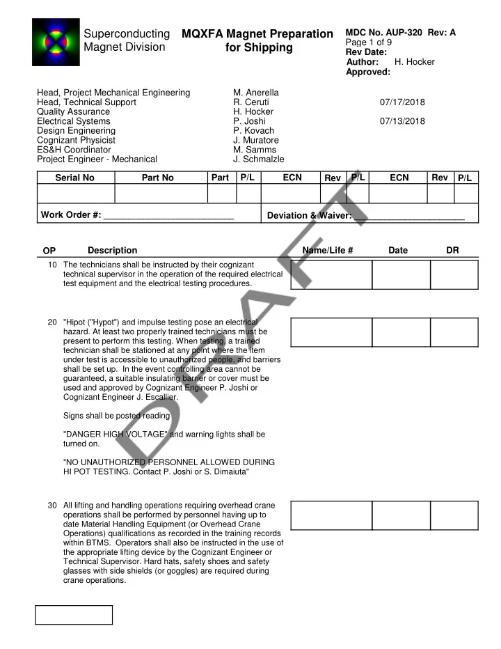
Rev Date: Page 1 of 9 Author: Approved:
MQXFA Magnet Preparation for Shipping
- H. Hocker
MDC No. AUP-320 Rev: A Head, Project Mechanical Engineering
- M. Anerella
Head, Technical Support
- R. Ceruti
07/17/2018 Quality Assurance
- H. Hocker
Electrical Systems
- P. Joshi
07/13/2018 Design Engineering
- P. Kovach
Cognizant Physicist
- J. Muratore
ES&H Coordinator
- M. Samms
Project Engineer - Mechanical
- J. Schmalzle
Serial No Part No Part P/L ECN Rev P/L ECN Rev P/L Work Order #: __________________________ Deviation & Waiver: ______________________ OP DR Date Name/Life # Description
10 The technicians shall be instructed by their cognizant technical supervisor in the operation of the required electrical test equipment and the electrical testing procedures. 20 "Hipot ("Hypot") and impulse testing pose an electrical
- hazard. At least two properly trained technicians must be
present to perform this testing. When testing, a trained technician shall be stationed at any point where the item under test is accessible to unauthorized people, and barriers shall be set up. In the event controlling area cannot be guaranteed, a suitable insulating barrier or cover must be used and approved by Cognizant Engineer P. Joshi or Cognizant Engineer J. Escallier. Signs shall be posted reading "DANGER HIGH VOLTAGE" and warning lights shall be turned on. "NO UNAUTHORIZED PERSONNEL ALLOWED DURING HI POT TESTING. Contact P. Joshi or S. Dimaiuta" 30 All lifting and handling operations requiring overhead crane
- perations shall be performed by personnel having up to