
SLIDE 1
Safety Management & Site Establishment Unit 10 Site Temporary - - PowerPoint PPT Presentation
Safety Management & Site Establishment Unit 10 Site Temporary Works Learning Outcomes How access to heights is gained and how structures are temporarily supported in the construction process Different styles of formwork for
How access to heights is gained and how structures are temporarily supported in the construction process Different styles of formwork for moulding concrete Excavation and trenching and other groundwork techniques
Temporary i.e. non-permanent works Temporary Works are installed on site to help fulfil the execution of the actual (permanent) contract works Temporary Works will be dismantled/removed from site upon fulfilment of their respective purposes. This Unit looks at four types of temporary works:
hydro-geological controls)
Frequently, temporary works play multiple roles but their selection is based on the primary project requirements This Unit details typical examples of the intertwined functions of temporary works to be expected on modern sites It also describes the indispensable roles that they typically function in every construction project These are roles that usually account for a significant percentage
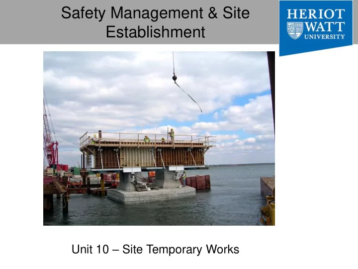
An example showcasing the extensive and combined utilities of temporary support and access structures.
Ladders should be a means
platform Main selection considerations will reside on suitability of work, safety/durability, cost and portability.
Easily available, ladders are essential as both the main and back-up tools of access
Must be positioned so as not to tip the scaffold Hook-on and attachable ladders must be specifically designed for use with the type of scaffold on which they are used Have rest platforms provided at a max. of 10m vertical intervals
When positioned their bottom step is not more than 24 inches above the scaffold supporting lever. Have rest platforms at maximum vertical intervals of 12 feet Have a minimum step width of 16 inches, except for mobile scaffold stairway-type ladders, which shall have a minimum step width of 11½ inches. Have slip-resistant treads on all steps and landings. Steps and rungs of ladders and stairway-type ladders shall line up vertically with each other between rest platforms.
Framed
Birdcage
ceiling, as well as to provide heavy-duty and sturdy falsework support for horizontal slab casting.
entire mass of support components can be easily shaped to provide horizontal support to massive areas.
loading pattern from the structure to the ground
17
18
Scaffold Types;
Working as a group; 1. Produce a sketch drawing of the each type, highlight main elements, 2. Find 3 examples works/cases/scenarios for each, when these scaffold types would be more useful than others, 3. Identify safety and practicality concerns for each type, 4. Identify safety and practicality benefits for each type,
materials to different working levels
system
and down the mast at a controlled speed
suspended cradles (described later in the Unit)
mobility of the access structures, especially so for retrofitting projects where clients are seeking short durations
Self-propelled and Vehicle-mounted
Articulated-telescopic boom Self-propelled Scissor platform
and capacities, from small trailer- mounted platforms to large truck- mounted types
in highway and other road-related maintenance (e.g. pruning trees, servicing street-lamps etc.)
access by other methods are deemed either too expensive
time- consuming
area of a project
working platform that can be positioned exactly to suit the task in hand
work site, together with the operatives
purposes only and must not be used for transporting men and materials between levels.
a platform capable of supporting persons & equipment and a chassis supporting the tower/mast
‘swing-stage scaffolds’ or ‘gondolas’, are perhaps the most common type of suspended scaffold.
the platform, they are commonly seen to be used by window cleaners on skyscrapers, and play a prominent role in high- rise construction
(or industrial roped access) can provide a safe and cost-effective method of access for light work commonly
maintenance or inspection nature.
and techniques allow fully trained specialist operatives to reach highly inaccessible locations, some of extreme conditions (e.g. from narrow mineshafts to
external details under apexes of skyscrapers).
It is a highly feasible method to consider if
conditions are either unknown
unsuitable to support any vertical access (e.g. crane, scaffold & the like).
cannot be reached from the ground (e.g. due to safety or physical constraints) and no strong anchorage points are available for gondolas.
maintenance of the main glass pyramid at Louvre Museum , France)
success of a project in terms of time, cost, quality and safety
achieve a very short floor cycle
appropriately designed formwork system.
size so the design and use of the right formwork system, will contribute substantially to the overall success of a project.
Kindly discuss the common formwork materials and types available in
used for formwork are traditionally limited due to the dilemma between cost and performance.
popular formwork material, due to its low initial cost and adaptability.
the performance is being questioned by many, particularly with regards to additional costs and the need for specialised workmen -
http://www.youtube.com/watch?feature=endscreen&v=Yqu21vPBylY&NR=1
with other sheeting materials, is another popular choice of formwork material.
Most timber and aluminium forms can be assembled manually, due to their weight, design and construction.
used in very large or complex buildings to attain the benefit in flexibility
erection and striking processes
lifted types or the mechanised slip-form systems.
steel sections and sheeting, or using plywood sheeting and stiffened by metal studs and soldiers.
fixed onto brackets (e.g. should they be used for external walls or shafts).
automated or manual), and these systems allow for continuous casting till the end of a typical section is reached.
construction of core walls in high-rise structures – lift shafts, stair shafts, towers, etc.
actually ‘slip off’ a previously cast structure
cementitious properties and composite bond with the reinforcements being set (i.e. harden) to a safe and acceptable level for the absence of the physical form support.
fixers and casting crew to adhere to appropriately timed and scheduled activities in order to compliment the continuum.
Repetitive sequence of work:
work and may be suitable for certain kinds of formwork.
repetitiveness will be limited Physical site constraints:
sloped grounds, minimal site access or manoeuvre space, close proximity to sensitive structures), will increase difficulties from the mobilisation stage (i.e. getting the formwork onto site and storing them) to subsequent erection.
Speed of work:
the introduction of additional sets of formwork to create more independent work sites.
time is of the essence e.g. when the risk of imposed delay penalties exceeds the costs of having additional systems
cannot often fulfil the need for speed in construction, as the critical path depends on individual floor-cycles times. Therefore the selected formwork design needs to support minimal floor-cycle times.
Recycling of formwork:
limited to its durability after every striking process (i.e. the removal
sheetings and left to dry, prior to the erection process
economically viable as the main option for formwork
and maintenance costs will often discourage its choice of use
Construction planning and management:
the structures, site-layout and setting up arrangements, and the hoisting and concrete placing facilities, etc., are influential factors in the selection and use of formwork. Area or volume of cast per pour:
accordance to the types of formwork used, elements of structure to be placed and specific scale of work
pour from approx. 10 safely-laden ready-mixed concrete trucks) to 200m3 (continuous pour involving (e.g.) elephant concrete pumps from approx. 40 trucks of the same) per pour can be comfortably planned for most site environments.
Formwork: Construction-related factors cont’d Continuity of structures and construction joints:
structure subdivides the works into effective and workable sizes,
are inevitable in all forms of building.
site staff exercise common sense, in conjunction with strict adherence to design specifications, to ensure the rigidity of a structure.
during the casting process, form-ties are incorporated into the formwork design
removed after casting, have their locations patched with high strength grout and should not affect the overall structural integrity of their structures.
Involvement of other construction techniques:
(http://www.youtube.com/watch?v=7JsuNg5r4Is) and
prefabrication techniques are often involved in the construction of modern high-rise buildings, especially so in the Far East.
and use of formwork, especially where pre-cast elements are to be incorporated during the casting process.
boxed-out positions in the formwork for the pre-cast elements, or additional working spaces for the placing of stressing tendons and the onward jacking process, should be allowed in such cases.
Excavations and trenching
in an earth surface that is formed by earth removal.
below the surface of the ground.
width (measured at the bottom) is not greater than 5m.
excavation reduces the distance between the form and the side of the excavation to 5m or less (measured at the bottom of the excavation), the excavation is also considered to be a trench.
Safety introduction:
construction operations and this Unit will highlight various trenching methods, hazards and their preventions.
Soil mechanics: An overview
cut site or trench. For example, increases or decreases in moisture content can adversely affect the stability of a trench
identified causes of trench failure.
TENSION CRACKS. Tension cracks usually form at a horizontal distance of 0.5 to 0.75 times the depth of the trench, measured from the top of the vertical face of the trench.
Figure 9.7.1: Tension Cracks
SLIDING or sluffing may occur as a result of tension cracks.
Figure 9.7.2: Sliding
cracks can cause toppling. Toppling occurs when the trench's vertical face shears along the tension crack line and topples into the excavation.
Figure 9.7.3: Toppling
SUBSIDENCE AND BULGING. An unsupported excavation can create an unbalanced stress in the soil, which, in turn, causes subsidence at the surface and bulging of the vertical face of the trench. If uncorrected, this condition can cause face failure and entrapment of workers in the trench.
Figure 9.7.4: Subsidence and Bulging
HEAVING OR SQUEEZING. Bottom heaving or squeezing is caused by the downward pressure created by the weight of adjoining soil. This pressure causes a bulge in the bottom of the cut, as illustrated in the drawing above. Heaving and squeezing can
properly installed.
Figure 9.7.5: Heaving or Squeezing
BOILING is evidenced by an upward water flow into the bottom of the cut. A high water table is one of the causes of boiling. Boiling produces a "quick" condition in the bottom of the cut, and can occur even when shoring or trench boxes are used.
Figure 9.7.6: Boiling
Ground shoring is the provision of a support system for trench walls, used to prevent movement of soil, underground utilities, roadways, and foundations. Shoring or shielding is used when the location or depth of the cut makes sloping back to the maximum allowable slope impractical. There are generally two types of shoring systems, each with its own sub-categories:
level and are commonly used in conjunction with trenching and sheet-piling systems to prevent the inward collapse of the surrounding earth.
structures that are deemed too structurally dilapidated to be in self-support, or as a falsework in support of the erection process
form of ground shoring support. The system consists of posts, wales, struts, and sheeting
components that resist the push factor from the surrounding earth
are timber and aluminium, the former being cheap and readily available, with the latter being strong and light
the use of hydraulic shoring, a prefabricated strut and/or wale system manufactured of aluminium or steel.
critical safety advantage over traditional strut shoring as workers do not have to enter the trench to install or remove the shoring components
different from shoring.
supporting the trench face, they are intended primarily to protect workers from cave-ins and similar incidents.
the trench should be as small as possible.
and the excavation side are backfilled to prevent lateral movement of the box.
69