
SLIDE 1
1
Struct uctur ural l Axial al, S Shear and and Bend Bending ng M Moment
- ments
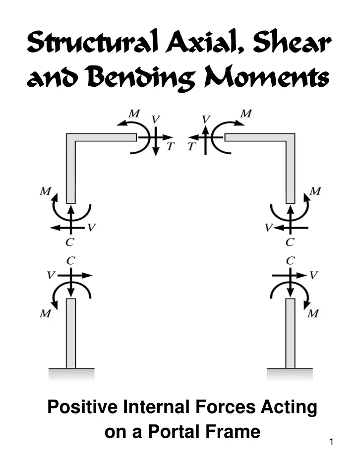
Positive Internal Forces Acting
- n a Portal Frame
Struct uctur ural l Axial al, S Shear and and Bend Bending - - PDF document
Struct uctur ural l Axial al, S Shear and and Bend Bending ng M Moment oments Positive Internal Forces Acting on a Portal Frame 1 Recall from mechanics of mater- ials that the internal forces P (generic axial), V (shear) and M
1
2
3
4
5
6
7
8
9
10
11
12
13
14
15
16
17
18
19
20
21
22
23
24
25
26
27
28
29
30
x y r
θ
31
32
θ θ
θ
33
34
35
36
37
38
39
40
41
42