
SLIDE 1
02 310 / G rev. 2 1/6 DIAGRAMS AND ADJUSTMENTS VALVE UNIT HSe250
Start Elevator
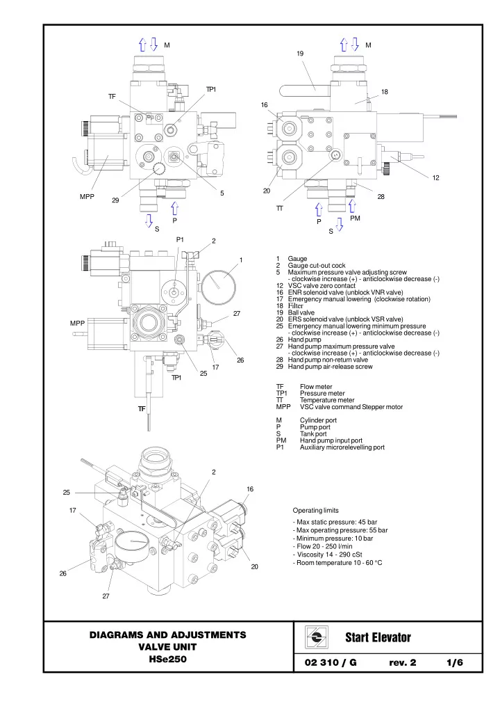
1 Gauge 2 Gauge cut-out cock 5 Maximum pressure valve adjusting screw
- clockwise increase (+) - anticlockwise decrease (-)
12 VSC valve zero contact 16 ENR solenoid valve (unblock VNR valve) 17 Emergency manual lowering (clockwise rotation) 18 Filter 19 Ball valve 20 ERS solenoid valve (unblock VSR valve) 25 Emergency manual lowering minimum pressure
- clockwise increase (+) - anticlockwise decrease (-)
26 Hand pump 27 Hand pump maximum pressure valve
- clockwise increase (+) - anticlockwise decrease (-)
28 Hand pump non-return valve 29 Hand pump air-release screw TF Flow meter TP1 Pressure meter T T Temperature meter MPP VSC valve command Stepper motor M Cylinder port P Pump port S Tank port PM Hand pump input port P1 Auxiliary microrelevelling port S P TF PM TP1 TF MPP TP1 MPP 16 20 19 18 25 17 T T 1 2 12 26 28 29 27 5 M M P S P1 TF 16 20 17 26 2 25 27 Operating limits
- Max static pressure: 45 bar
- Max operating pressure: 55 bar
- Minimum pressure: 10 bar
- Flow 20 - 250 l/min
- Viscosity 14 - 290 cSt
- Room temperature 10 - 60 °C