
1
ME 499-699 Fall 2006 Slides 8 -1Process Selection Case Studies
Aerospace part - Elevator control quadrant Casing for an electric plug Ceramic valve Plastic bottle
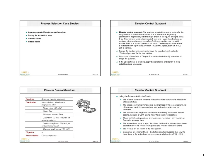
ME 499-699 Fall 2006 Slides 8 -2Elevator Control Quadrant
- Elevator control quadrant: The quadrant is part of the control system for the
wing-elevator of a commercial aircraft. It is to be made of a light alloy (aluminum or magnesium) with the shape shown in the figure. It weighs about 5 kg. The minimum section thickness is 5 mm, and – apart from the bearing surfaces – the requirements on surface finish and precision are not strict: surface finish ≤ 10 μm and precision ≤ 0.5 mm. The bearing surfaces require a surface finish ≤ 1 μm and a precision ≤ 0.05 mm. A production run of 100 – 200 is planned.
a)
Itemize the function and constraints, leave the objective blank and enter “Choice of process” for the free variable.
b)
Use copies of the charts of Chapter 7 in succession to identify processes to shape the quadrant.
c)
If the CES software is available, apply the constraints and identify in more detail the viable processes.
ME 499-699 Fall 2006 Slides 8 -3Elevator Control Quadrant
Choice of process Free variables
- Objective
Planned batch size of 100 - 200 Surface roughness: 10 μm (1 μm
- n bearing surfaces)
Tolerance: 0.5 mm, (0.05mm on bearing surfaces) Minimum section: 5 mm Mass: 5 kg Shape class: 3D-solid Material class: aluminum or magnesium alloy Constraints Shape an elevator quadrant Function
ME 499-699 Fall 2006 Slides 8 -4Elevator Control Quadrant
Using the Process Attribute Charts
- The material constraint limits the selection to those shown in the first column
- f the next chart.
- The shape constraint eliminates two, leaving those in the second column. All
- f these can meet the constraints on size and section, which are not
restrictive.
- The tolerance and roughness constraints on the body are not met by sand
casting, though it is worth asking if they have been overspecified.
- Those on the bearing surfaces are much more restrictive – only machining
from solid achieves them.
- The answer here is not to reject the others, but to add a finishing step, shown
at the bottom of the Process-Roughness and Process-Tolerance charts
- The result is the list shown in the third column.
- Economics are important here – the batch-size chart suggests that only the
three listed in the last column are economic at a batch size of 100 – 200.