
SLIDE 1
IIT Bombay
CE 303 23 Instructor: AJ
25/09/2009 Lecture: 23
Soil with water Sub-topics Seepage forces & Quick sand conditions
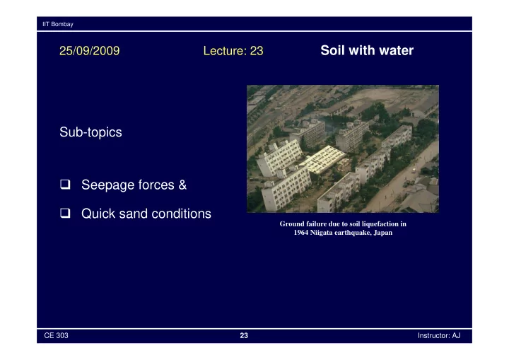
Ground failure due to soil liquefaction in 1964 Niigata earthquake, Japan
Soil with water 25/09/2009 Lecture: 23 Sub-topics Seepage forces - - PowerPoint PPT Presentation
IIT Bombay Soil with water 25/09/2009 Lecture: 23 Sub-topics Seepage forces & Quick sand conditions Ground failure due to soil liquefaction in 1964 Niigata earthquake, Japan CE 303 23 Instructor: AJ IIT Bombay Seepage forces
IIT Bombay
CE 303 23 Instructor: AJ
Ground failure due to soil liquefaction in 1964 Niigata earthquake, Japan
IIT Bombay
CE 303 23 Instructor: AJ
IIT Bombay
CE 303 23 Instructor: AJ
IIT Bombay
CE 303 23 Instructor: AJ
IIT Bombay
CE 303 23 Instructor: AJ
IIT Bombay
CE 303 23 Instructor: AJ
IIT Bombay
CE 303 23 Instructor: AJ
IIT Bombay
CE 303 23 Instructor: AJ
IIT Bombay
CE 303 23 Instructor: AJ
IIT Bombay
CE 303 23 Instructor: AJ
Effective stress is decreased by
IIT Bombay
CE 303 23 Instructor: AJ
http://picasaweb.google.com/melaniejbonk
IIT Bombay
CE 303 23 Instructor: AJ
IIT Bombay
CE 303 23 Instructor: AJ
IIT Bombay
CE 303 23 Instructor: AJ
IIT Bombay
CE 303 23 Instructor: AJ
IIT Bombay
CE 303 23 Instructor: AJ
IIT Bombay
CE 303 23 Instructor: AJ
IIT Bombay
CE 303 23 Instructor: AJ
Image courtesy NASA/GSFC/LaRC/JPL