
SLIDE 1
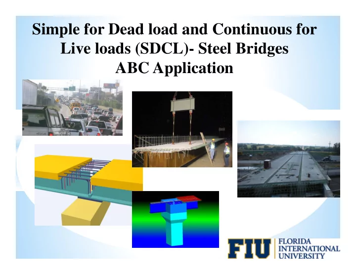
Simple for Dead load and Continuous for Live loads (SDCL)- Steel Bridges ABC Application
Simple for Dead load and Continuous for Live loads (SDCL)- Steel - - PowerPoint PPT Presentation
Simple for Dead load and Continuous for Live loads (SDCL)- Steel Bridges ABC Application Summary of more than ten years of research, field application and monitoring Aaron Yakel- University of Nebraska-Lincoln Reza Farimani, Thornton Tomasetti
Simple for Dead load and Continuous for Live loads (SDCL)- Steel Bridges ABC Application
Summary of more than ten years of research, field application and monitoring Aaron Yakel- University of Nebraska-Lincoln Reza Farimani, Thornton Tomasetti Saeed Javidi, Associated Engineering, CA Derek Kowalski, NUCOR Nazanin Mossahebi, Bureau Veritas North America Nick Lampe, HDR Results of the study are summarized in five journal paper and submitted to special issue of AISC EJ for possible publications
Summary of more than ten years of research, field application and monitoring Nebraska Department of Roads Federal Highway Administration
Typical Construction of Steel Bridges Continuous for Dead and Live Loads
Falsework Restricted Traffic Pier Field Splice Field Splice
Typical Steel Construction - Continuous for Dead and Live Loads
In the slides to follow:
Simple for Dead load and Continuous for Live loads
SDCL- Conventional Case- cast in place deck
SDCL- ABC Case- Modular approach
Dead Loads Live Loads
SDCL System
SDCL Steel Bridge System More than one way to provide continuity for live loads
SDCL Bridge System using Concrete Diaphragm
For most part connections that works for cast in place deck methods of construction, also works for ABC applications
Creep and shrinkage is not an issue
Advantages of Concrete Diaphragm
Protects the ends of the girders and enhances service life
Prestressed Concrete Steel Large Bottom Flange Small Bottom Flange
Challenges using Concrete Diaphragm
Bottom flang Bottom flange continuous continuous plus plus end plate end plate
Connected bottom flanges End plates
ULTIMATE LOAD TEST
End Plate onl End Plate only
No No End End De Detail il
1000 2000 3000 4000 5000 6000 7000 0.005 0.01 0.015 0.02 0.025
Drift= D/L (in/in) Moment=M (kips-ft) Test 1 Test 2 Test 3
D M L
Important consideration when Using concrete diaphragm
It is important to provide continuous load path for transferring the compression force from one flange to the next flange, without the possibility
Calculating the tension reinforcement
T
Strain
bf bs e
s
ey y
y se
be Fy
Stress
Fs
Strain and Stress in Slab
Stress
bf bs q 1/2Foc Fq 1/2Foc
Stress in Concrete Diaphragm
Resisting Elements Test 1 Test 3
Slab Rebar 60.82% 66.77% Stirrups in tension 5.09% 5.42% Concrete in tension 4.35% 6.03% Stirrups in compression 0.00% 1.58% Concrete in compression 12.37% 20.20% Bottom plate in compression 17.37% NA Total 100.00% 100.00%
C T Moment Arm
T C
Example: Two span steel bridge using SDCL system- Each span 95 ft.
Live load moment Mu (LL)= 34770 in-kip Girder size W40x249 Depth of girder 43.375” As= 34770 / (60 * (43.375 – 4 / 2))= 14 in2 As= Mn / ( fy (d- H/2) )
Use of recommended detail for SDCL Cast in place deck vs ABC
T C
SDCL- Cast in Place Deck
End of girders needs to be restrained against twist before casting deck
SDCL- Cast in Place Deck
Recommendation is to fill the concrete diaphragm about ½ to 2/3 of the height and let it cure
SDCL- Cast in Place Deck
SDCL – Cast in Place Deck
SDCL- Cast in Place Deck
To minimize the cracking
SDCL – Cast in Place Deck
Recommendation- Assume 20% continuity for dead load
Use of the recommended detail
T C
SDCL- Case of ABC
SDCL- Case of ABC
SDCL- Case of ABC
T C
SDCL- Case of ABC
SDCL- Case of ABC
Full Scale Testing SDCL- ABC recommended detail
Full Scale Testing SDCL- ABC recommended detail
Full Scale Testing SDCL- ABC recommended detail
50 100 150 200 250 300 350 400 450
1 2 3 4 5 6 7
Load (kips) Displacement (in) East Span
East West
Pier
SDCL- Recommended Detail Cast in Place Deck ABC Fill Diaphragm ½ to 2/3
Girder Cope Top Flange Bearing Blocks Deck Longitudinal Reinforcement
Recommended Design – Tension Reinforcement Cast in Place Deck ABC
Mn=Asfy (moment Arm)
Future Applications of SDCL- Seismic Application Steel bridges are lighter (about 40% of concrete bridges) 1995 Hyogoken-Nanbu earthquake in Kobe lesson: Protect end of steel girder and have a good path to transfer lateral loads from superstructure to substructure. Hanshine Expressway, was closed for more than a year
Future Applications of SDCL- Seismic Application
Future Applications of SDCL- Seismic Application
Girder Cope Top Flange Bearing Blocks Deck Longitudinal Reinforcement
Brief Discussion of other SDCL Details used in Practice
Test results shows that concrete in vicinity of Bottom flanges can crush
50 100 150 200 250 300 350 400 450 0.05 0.1 0.15 0.2 0.25 0.3 0.35 0.4 Displacement=D (in) Load (kips) East Girder West Girder D West East Research results shows that there is no need for top plate
Challenges with this detail (Cast in Place Deck)
girder.
Challenges with this detail (Cast in Place Deck)
Advantages of SDCL Steel Bridge System Cast in place deck and ABC
ABC
Advantages of SDCL Steel Bridge System Cast in place deck and ABC
Advantages of SDCL Steel Bridge System Cast in place deck and ABC
throughout the girder length
recommended detail over pier, protect the girder ends against any possible corrosion and enhances the service life of bridges. Eliminating the bolted splices, also help to enhance the service Advantages of SDCL Steel Bridge System Cast in place deck and ABC
AISC Engineering Journal special edition- SDCL
existing S DCL expertise in one place for easy reference to facilitate standardization of design and construction practices
construction, or monitoring in- service performance of S DCL steel bridges
ubmittals due January 11, 2013
www.aisc.org/ej
Thanks You Contact Information Atorod Azizinamini