
SLIDE 1
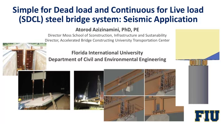
Simple for Dead load and Continuous for Live load (SDCL) steel bridge system: Seismic Application
1
Atorod Azizinamini, PhD, PE
Director Moss School of Sconstruction, Infrastructure and Sustanability Director, Accelerated Bridge Constructing University Transportation Center
Florida International University Department of Civil and Environmental Engineering