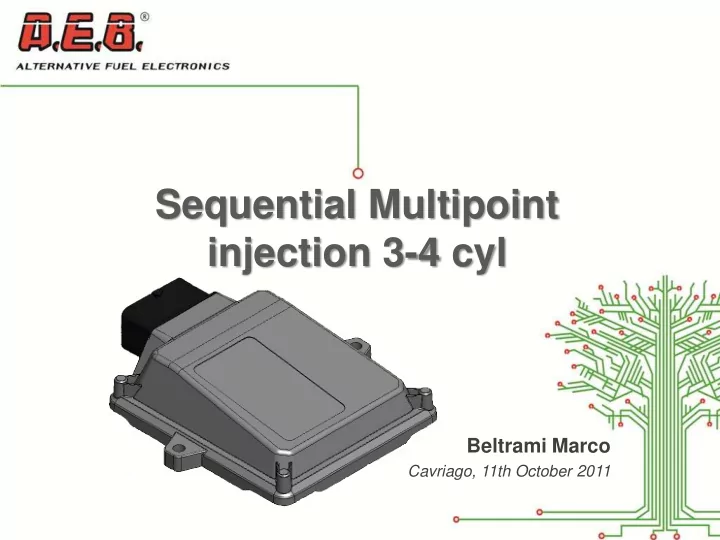

Sequential Multipoint injection 3-4 cyl Beltrami Marco Cavriago, 11th October 2011
Electrical Characteristics Supply voltage: V batt = 10 ÷ 16V Working Temperature Range: -40 ÷ 105 ° C Quiescent current (actuators inhibited): I max ≤ 0.5A Quiescent Current in standby: I standby ≤ 5mA Injectors: I max = 6A, V batt,max = 16V Gas Valves (2 output): P max = 50W, I max = 4 A (single common output) P max = 25W, I max = 2 A (two indipendent output) 1
Sensors Gas Pressure Sensor: AEB025, new PTM MAP Sensor: AEB025, new PTM, Original Gas Temperature Sensor: 4K7, 2k2 Water Temperature Sensor: 4K7, Original Gas Level Sensor: AEB, 0-90 Ω , not standard, not standard inverted Lambda Probe: 0-1V, 0-5V, 5-0V, 0.8-1.6V
Monoplug vs other ECUs Feature AEB2001NC AEB2001PC Monoplug Χ Extended map (12x12) Progressive petrol to gas swicth Petrol addition management Χ (idle, addition, high RPM) Χ Diagnosys on gas injectors Real time diagnosys on petrol injectors connection Diagnosys on sensors and change over swicth Χ Gas injectors enable/disable for diagnistic purpose Χ RPM reading from negative coil or Injection time
Monoplug vs other ECUs Feature AEB2001NC AEB2001PC Monoplug Χ Split fuel option Χ Start & Stop vehicle managment Χ Lambda probe reading and emulation (just reading one (two channel) (one channel) channel) Χ Multilayer board Χ Χ Linear Lambda probe emulation Χ Χ OBD II parameter reading and visualization Χ Χ OBD II Adaptativity Χ Χ Low standby current (Iq < 10µA)
Interchangeable Compatibility with actual software (V>x.x.x) Compatibility with actual configurations Compatibility with actual kits Χ Compatibility with actual harnesses Χ Compatibility with actual firmwares
Diagram
Harness drawing Serial Water Temperature Gas Level Sensor PTM Lambda Probe EV Gas 2 Gas Injectors Petrol cut injectors Power Supply EV Gas 1 RPM Switch
Installation drawing
PTM sensor: gas Pressure and Temperature, MAP GAS Type: LPG/CNG Power Supply: 5 ± 0.2 V Map signal Output range: 0.5 ÷ 4.5 V Pressure signal Output range: 0.5 ÷ 4.5 V Temperature range: -40 ÷ 125°C Maximum Gas Pressure: 4.5 Bar
New PTM sensor: Mechanical installation Manifold Pressure (MAP) Pressure Reducer Out GAS GAS Injectors PTM Sensor (Pressure Intake manifold Temperature MAP)
Injectors rail Highlights ▪ Two Injectors families ▪ Aluminum ▪ Polymer ▪ Both version accept different hole size on same body ▪ High pressure up to 7 bar CNG ▪ Easy maintenance ▪ Cost/performance ratio ▪ Polymer version has better performances (repeatability, cold conditions, endurance) Aluminum version with integrated sensor Polymer version
A.E.B. S.P.A. a socio unico Via dell’Industria 20 | 42025 Cavriago (RE) | Italia Ph. +39 0522 494401 | fax +39 0522 494410 | info@aeb.it | www.aeb.it
Recommend
More recommend