
SLIDE 1
1
- Dept. of Civil, Structural & Environmental Eng. , University at Buffalo
APPLICATIONS OF SEISMIC PROTECTIVE SYSTEMS IN OFFSHORE GAS AND OIL PLATFORMS Michael C. Constantinou
Department of Civil, Structural, and Environmental Engineering University at Buffalo, State University of New York
- Dept. of Civil, Structural & Environmental Eng. , University at Buffalo
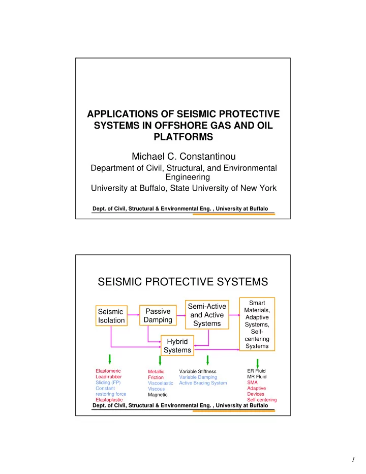
SEISMIC PROTECTIVE SYSTEMS
Hybrid Systems Seismic Isolation Passive Damping Semi-Active and Active Systems
Smart Materials, Adaptive Systems, Self- centering Systems
Elastomeric Lead-rubber Sliding (FP) Constant restoring force Elastoplastic Metallic Friction Viscoelastic Viscous Magnetic Variable Stiffness Variable Damping Active Bracing System ER Fluid MR Fluid SMA Adaptive Devices Self-centering