
SLIDE 1
Utah School of Computing Spring 2013 Computer Graphics CS5600
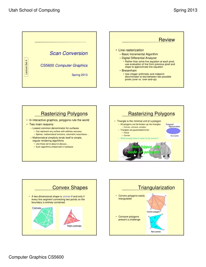
Scan Conversion
CS5600 Computer Graphics
Spring 2013
Lecture Set 4
Review
- Line rasterization
– Basic Incremental Algorithm – Digital Differential Analyzer
- Rather than solve line equation at each pixel,
use evaluation of line from previous pixel and slope to approximate line equation
– Bresenham
- Use integer arithmetic and midpoint
discriminator to test between two possible pixels (over vs. over-and-up)
Rasterizing Polygons
- In interactive graphics, polygons rule the world
- Two main reasons:
– Lowest common denominator for surfaces
- Can represent any surface with arbitrary accuracy
- Splines, mathematical functions, volumetric isosurfaces…
– Mathematical simplicity lends itself to simple, regular rendering algorithms
- Like those we’re about to discuss…
- Such algorithms embed well in hardware
Rasterizing Polygons
- Triangle is the minimal unit of a polygon
– All polygons can be broken up into triangles
- Convex, concave, complex
– Triangles are guaranteed to be:
- Planar
- Convex
– What exactly does it mean to be convex?
Convex Shapes
- A two-dimensional shape is convex if and only if
every line segment connecting two points on the boundary is entirely contained.
Triangularization
- Convex polygons easily
triangulated
- Concave polygons