Resource ConservationTraining 27 January 2016 Conserving Energy in - - PDF document

resource conservationtraining 27 january 2016
SMART_READER_LITE
LIVE PREVIEW

Resource ConservationTraining 27 January 2016 Conserving Energy in - - PDF document

Resource ConservationTraining 27 January 2016 Conserving Energy in Presentation Outline Compressed Air Systems How Much Does CAir Cost -Introduction Presented to the Supply Side Components how they perform and work together


slide-1
SLIDE 1

Resource ConservationTraining 27 January 2016 1

Conserving Energy in Compressed Air Systems

Presented to the MA Toxic Use Reduction Institute Resource Conservation Training January 27, 2016 By Jim Guertin, P.E., AIRMaster+ Specialist UTS Energy Engineering 617-471-3454 jim@UTSee.com

Presentation Outline

  • How Much Does CAir Cost -Introduction
  • Supply Side

– Components – how they perform and work together – Where to look for savings

  • Demand Side

– System components – Appropriate and inappropriate uses – Control Issues – Where to look for savings

Welcome to the Wonderful World of Compressed Air

CAir analysis needs a different mind set. Example: A leak is blowing out 100 CFM Questions: Will more air be wasted at 50 psi or 100 psi? Will more energy be wasted at 50 psi or 100 psi?

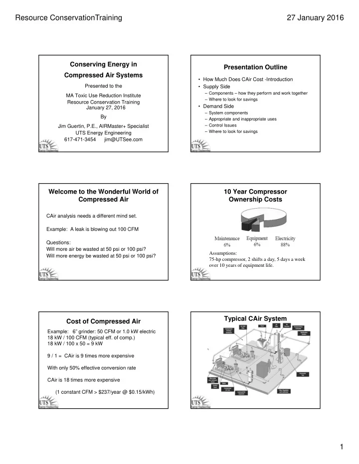
10 Year Compressor Ownership Costs

Assumptions: 75-hp compressor, 2 shifts a day, 5 days a week

  • ver 10 years of equipment life.

Cost of Compressed Air

Example: 6” grinder: 50 CFM or 1.0 kW electric 18 kW / 100 CFM (typical eff. of comp.) 18 kW / 100 x 50 = 9 kW 9 / 1 = CAir is 9 times more expensive With only 50% effective conversion rate CAir is 18 times more expensive (1 constant CFM > $237/year @ $0.15/kWh)

Typical CAir System

slide-2
SLIDE 2

Resource ConservationTraining 27 January 2016 2

Supply Side Components

  • Compressors

–Controls

  • Dryers

–Controls

  • Traps
  • Receiver
  • Filters

Types of Compressors

Operating Range of Compressor Types Double Acting 2 Stage Reciprocating Double Acting 2 Stage Reciprocating

slide-3
SLIDE 3

Resource ConservationTraining 27 January 2016 3

Small On/Off Reciprocating Reciprocating Compressor Controls

  • On / Off
  • Step Unloading

Centrifugal Compressor Centrifugal Compressor Centrifugal Compressor Control

  • Modulating

– Inlet Guide Vanes – Butterfly Valve

  • Dual / Auto Dual
slide-4
SLIDE 4

Resource ConservationTraining 27 January 2016 4

Screw Compressor Cut Away of a Screw Screw Geometry Control Screw Compressor Controls

  • Modulating (Inlet Valve)
  • Load / Unload
  • Dual / Auto Dual
  • Geometry (Turn/Spiral, Poppet valves)
  • Variable Speed
  • Effects of Receiver Size
slide-5
SLIDE 5

Resource ConservationTraining 27 January 2016 5

10 20 30 40 50 60 70 80 90 100 110 10 20 30 40 50 60 70 80 90 100

% of Full Load BHP

% of Full Load CFM

Screw Compressor Control Comparisons

Inlet Modualtion Geometry Online/Offline 3 gal/cfm VSD On / Off

On-Line/Off-Line Cycle

CAGI Compressor Data Sheet Rotary Compressor: Fixed Speed CAGI Compressor Data Sheet Rotary Compressor: Variable Speed Drive

Air Compressor Curve Tool.XLS -- INPUTS

slide-6
SLIDE 6

Resource ConservationTraining 27 January 2016 6

Air Compressor Curve Tool.XLS OUTPUTS

0% 10% 20% 30% 40% 50% 60% 70% 80% 90% 100% 110% 0% 20% 40% 60% 80% 100% % of Full Load KW % of Full Load CFM

COMPRESSOR #1 From TAB: Outputs - Curves From TAB: Outputs - Tables

Air Compressor Curve Tool.XLS Compressor Control Type

Other Common Types of Compressors

  • Liquid Ring
  • Sliding Vane
  • Axial
  • Lobe

Liquid Ring Air Compressor

Sliding Vane Compressor Axial Compressor

slide-7
SLIDE 7

Resource ConservationTraining 27 January 2016 7

Lobe Compressor Compressor Conservation Measures

  • Lower operating pressure

– 1% savings for each 2 psi drop

  • Coordinate control of multiple comps

– Partly load only one compressor

  • Add storage for on-line/off-line

controlled compressors

  • Get intake air from outside
  • Turn off during unoccupied times

Refrigerated Dryer Non-Cycling Cycling

Dew points to 28 F

Cold Regeneration Desiccant Dryer

Dew points to - 90 F Purge ~ 20% of rated

slide-8
SLIDE 8

Resource ConservationTraining 27 January 2016 8

Desiccant Dryers

Internal heat reactivated External heat reactivated Dew points to - 40 F Dew points to - 40 F Purge ~ 5% of rated Purge ~ 2% of rated

Heat Of Compression Dryer Dryer Conservation Measure

For ~ 35F dew points

  • Replace non-cycling refrigerated dryer

with cycling refrigerated dryer

  • Clean air-cooled condenser

For < 20F dew points

  • Install heat of compression dryer
  • Install dew point control on desiccant

dryers

Receiver Location – Before Dryer

Advantages:

– Favorable dryer size. – Non-turbulent flow – Lower CAir entry temp. – Lower condensate amount

Disadvantages:

– Condensate in receiver – Overload of the Dryer

Receiver Location – After Dryer

Advantages:

– No condensate in receiver – Consistent CAir quality

Disadvantages:

– Large size dryer – Stress with Recip. – High entry temp of CAir – Large quantity of condensate – Each compressor has its

  • wn dryer

CAGI Dryer Data Sheet Refrigerated Dryers

slide-9
SLIDE 9

Resource ConservationTraining 27 January 2016 9

Timed Cycle Trap

– Very reliable operation – Electricity connection required – No alarm function – Operates all the time no matter the CAir load – Doesn’t differentiate between air and water

Air and Water Leakage.XLS Electronic Level Sensing Trap

– Very reliable operation even with problematic condensates – Large discharge – No pressure loss – Electricity connection required – Alarm function – External malfunction signal.

3 4 1 5

Mechanical Float Trap

– Very reliable

  • peration even with

problematic condensates – Large discharge – No pressure loss – Electricity connection required – Alarm function (at 3)

Trap Conservation Measure

  • Avoid manual blow down
  • Replace Timed Cycle Trap
  • Periodically check traps for proper
  • peration
  • Periodically clean traps
slide-10
SLIDE 10

Resource ConservationTraining 27 January 2016 10

Filters

Particulate

  • Dust separator > 50 micron
  • Pre-filter > 3 micron
  • Micro filters > 0.01 micron

Coalescing

  • Removes particles, moisture and oil to 0.1

microns

Filter Conservation Measures

  • Replace with low pressure drop filters

– Will only save energy if compressor operating pressure reduced ( 1% kW saved for each 2 psi drop )

Supply Side Conservation Measures

ECO Savings

Low pressure drop inlet filter 2% More efficient compressor 10-15% Replace/Stop leaking isolation valve 10-20 cfm Micro processor sequencer shut off idling compressor, reduce deadband Replace condensate traps 40-80 cfm Replace filters 3-10 psi Replace dryer >50% of dryer usage

Demand Side of Typical Industrial CAir User Demand Side Components

Distribution System

  • Demand Expander /

Intermediate Pressure Controller

  • Piping
  • Hoses
  • FLR (filter, lubricator, regulator)
slide-11
SLIDE 11

Resource ConservationTraining 27 January 2016 11

Demand Expander

  • A very quick acting full bore pressure reducer

Advantages

  • Reduces leakage
  • Reduces artificial demand
  • Adds capacitance to system

Disadvantage

  • Requires compressor to operate at higher

pressures

Demand Side Components

End Uses

  • Productive uses
  • Inappropriate uses
  • Leakage
  • Artificial demand

Demand Side Conservation Measures

Reduce Productive Usage

  • Replace nozzles with engineered nozzles
  • Purchase more conservative equipment

Demand Side Conservation Measures

Inappropriate Uses of CAir

See Handout: Potentially Inappropriate Uses of Compressed Air

slide-12
SLIDE 12

Resource ConservationTraining 27 January 2016 12

Demand Side Conservation Measures

Reduce Artificial Demand

  • Demand Expander / Pressure Controller
  • Remote Storage
  • End Use Pressure Regulators
  • Reduce System Pressure
  • Loop Header
  • Enlarge Piping
  • Low Pressure Drop Filters

and other components

Demand Side Conservation Measures

Testing For Leakage

  • Ultrasonic leak detector
  • Receiver bleed down test

P1 = start pressure, psig P2 = end pressure, psig Volume is in cubic feet Time is in minutes Leakage, CFM = Volume * ( P1 - P2) * 1.25 Time * 14.7

If leakage is > than 10% of compressor capacity action should be taken

Reduce Leakage

  • Perform Detailed Survey
  • Make Leak Repairs
  • Institute On Going Leak Reduction

Program

Heat Recovery

slide-13
SLIDE 13

Resource ConservationTraining 27 January 2016 13

Available Heat To Recover Compressor Heat Calculator.XLS Demand Side Conservation Measures

ECO Savings

Demand Expander / Pressure regulator 10 - 15 psi Leaks, quick disconnects, open nozzles 10% or more Point of use storage 5 - 10 psi Complete loop 2.5 - 5 psi New main 3 - 8 psi New drops 2 - 6 psi

Rules Of Thumb

  • Air compressors normally deliver 4 to 5 cfm per

horsepower at 100 psi

  • Every 2 psi pressure change in pressure equals 1%

change in compressor power draw

  • Power cost for each hp operating constantly for 1 year =

$1,100 @ 15¢/kwh

  • A 50 hp compressor rejects heat at about 126,000 btu/h

and about 119,000 (> 90%) is recoverable

  • Water vapor content of 100ºF saturated compressed air

= ~ 2 gallons per hour per 100 cfm

  • Every 100 cfm of 100 psig air produces 20 gallons of

condensate per day

Rules Of Thumb

  • Total pressure drop across all components should not be

greater than 15 psi

  • Locate filters and dryers in the air line before any

pressure reducing valve (highest pressure) and after air is cooled to 100ºF or less (lowest temperature)

  • Water cooled after coolers require ~ 3 gpm per 100 cfm

@100 psig

  • Most air motors require 30 cfm at 90 psig per

horsepower rating

  • At 100 psig every 20ºF increase in saturated air temp

DOUBLES the amount of moisture in the air