Remote Mine Identification from Man-Portable UUVs Chris Gilson 1 1 - - PDF document

remote mine identification from man portable uuv s
SMART_READER_LITE
LIVE PREVIEW

Remote Mine Identification from Man-Portable UUVs Chris Gilson 1 1 - - PDF document

UDT 2020 Remote Mine Identification from Man-Portable UUVs 2G Robotics Remote Mine Identification from Man-Portable UUVs Chris Gilson 1 1 Product Development Manager, 2G Robotics, Waterloo Canada cgilson@2grobotics.com Abstract


slide-1
SLIDE 1

UDT 2020 Remote Mine Identification from Man-Portable UUVs 2G Robotics

Remote Mine Identification from Man-Portable UUV’s

Chris Gilson1

1Product Development Manager, 2G Robotics, Waterloo Canada – cgilson@2grobotics.com

Abstract — Unmanned Underwater Vehicles (UUVs) are becoming the platform of choice for modern mine countermeasure (MCM) operations. Advantages of reduced platform cost and improved mission efficiency are already being realized through their use for mine detection with side-scan sonar. However, for UUV’s to reach their full potential they must be able to perform remote visual identification in order to reduce the frequency of clearance diver deployments into the minefield. This paper discusses the challenges associated with developing a camera payload for man-portable UUVs, including power constraints, imaging at high speed, turbidity, size limitations, and data workflow. An MCM operational process is outlined for using such a system to conduct Remote Mine Identification after detection and localization of mine-like-

  • bjects (MLO) is completed with a side-scan sonar survey. Using the 2G Robotics Mine Identification Payload on

Hydroid REMUS vehicles, it is demonstrated that high-resolution stills image data can be used to obtain visual identification of mine targets with a high degree of confidence. Automated software is employed to use side-scan sonar target files to efficiently extract target data from large image datasets in order to increase the operational tempo of MCM missions. High resolution camera payloads deployed on man-portable UUVs have the potential to improve MCM mission efficiency and reduce risk by limiting the time that divers and vessels are in the minefield. Continued operational testing by the REMUS users and the MCM community will determine whether this solution will become a standard part of modern mine countermeasure operations.

1 Introduction

Unmanned Underwater Vehicles (UUVs) are rapidly becoming an essential platform for modern mine countermeasure (MCM) operations. Their adoption offers increased operational efficiency, reduced platform cost, and a reduction in risk by removing personnel and vessels from the minefield. However, to truly change how MCM

  • perations are executed these vehicles must evolve to offer

Remote Mine Identification capability that reduces the reliance on clearance divers for performing visual identification. An MCM operation consists of 4 stages: Detection, Classification, Identification, and Disposal/Neutralization [1]. With today’s UUV platforms, mine detection is completed using side-scan sonar and, in some cases, classification can be achieved using high resolution synthetic aperture sonar (SAS). However, a vessel must then enter the minefield to deploy a clearance diver or a remotely operated vehicle (ROV) to complete the visual identification stage. This is particularly time consuming in areas with complex seabed since the limited resolution of sonar leads to a high probability of false detection and therefore many unnecessary diver deployments. The commercial sector has proven that sonar data can be augmented with high resolution optical data to reduce the uncertainty involved in underwater sonar surveys [2]. This is particularly relevant for subsea oil and gas pipeline inspection where multibeam sonar on UUVs has been supplemented with and high-resolution images and 3D laser data to reduce the risk of missing critical defects [2]. In this application, laser and image data have enabled the adoption of automated data analysis where pipeline defects can be identified automatically. Machine vision is used to detect and highlight features of interest, reducing the amount of data that an operator must analyze manually and significantly reducing data analysis time. This paper outlines the development challenges and trade-

  • ffs associated with miniaturizing the 2G Robotics camera

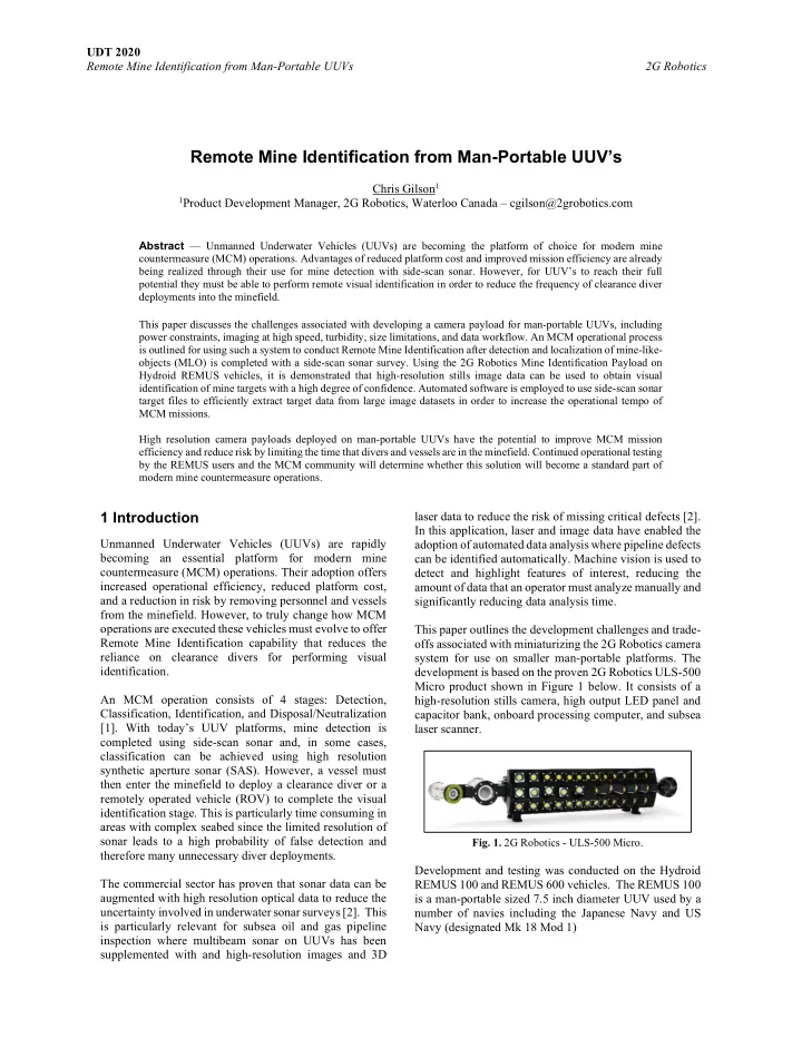
system for use on smaller man-portable platforms. The development is based on the proven 2G Robotics ULS-500 Micro product shown in Figure 1 below. It consists of a high-resolution stills camera, high output LED panel and capacitor bank, onboard processing computer, and subsea laser scanner.

  • Fig. 1. 2G Robotics - ULS-500 Micro.

Development and testing was conducted on the Hydroid REMUS 100 and REMUS 600 vehicles. The REMUS 100 is a man-portable sized 7.5 inch diameter UUV used by a number of navies including the Japanese Navy and US Navy (designated Mk 18 Mod 1)

slide-2
SLIDE 2

UDT 2020 Remote Mine Identification from Man-Portable UUVs 2G Robotics

  • Fig. 2. Hydroid REMUS 100

The REMUS 600 is a mid-sized 12.75 inch diameter UUV used by a number of navies including the UK Royal Navy and US Navy (designated Mk 18 Mod 2)

  • Fig. 3. Hydroid REMUS 600

Testing was aimed at evaluating the capability of the Mine Identification Payload on small UUV platforms for performing visual identification

  • f

mine targets. Specifically, the aim was to determine if this optical payload could successfully identify MLOs with the same level of certainty as a clearance diver. The Mine Identification Payload includes a stills camera and high power LED panel to capture 12-megapixel (4K) resolution images of targets with even illumination and high contrast. Imaging can take place at long ranges up to 7 meters altitude and at speeds of up to 4 knots. The payload incorporates an on-board computer for real-time image enhancement and stores images either on a local hard-drive

  • r an external removable storage device.

2 Development & Challenges

The development of a camera system for man-portable UUVs presents various technical challenges that were

  • vercome to deliver high quality images. These challenges

and the resulting design solutions are outlined in this section. 2.1 Power Constraints Small UUVs have a significantly lower power capacity than larger vehicles that have historically used high resolution optical payloads (eg. REMUS 100 has 1 kW-hr battery capacity compared to 62.5 kW-hr on a HUGIN Superior). With this constraint in mind, the power draw design requirement was defined as a maximum average power draw of 50 watts which ensures the vehicle maintains a usable endurance level. This limitation required significant changes to the 2G camera system which are discussed below. The largest contributor to power draw in a camera system is the artificial light source. For this reason, an LED strobe was selected instead of a continuous light source in order to reduce power draw. A strobe lighting system is designed with a capacitor bank that draws consistent power from the vehicle battery to charge up capacitors that deliver the accumulated power in short, high-intensity bursts via the

  • LEDs. This allows for very high light power (>200,000

lumens) to be output during short camera exposure times. LED strobe power consumption is defined by the camera frame rate (Hz), LED output intensity and the camera exposure time (ms), as shown in the below equation. Minimizing each of these factors was explored in the system design to reduce power draw, while simultaneously trying to maximize the lighting output efficiency of the system. Power draw∝ Frame Rate x Intensity x Exposure time (1) To reduce the required frame rate, a dome viewport was integrated into the camera module to increase the along- track field-of-view to 63 degrees. This allows for a frame rate of less than 1 Hz to be used while still achieving a 45%

  • verlap on successive images when operating at 3 meters

altitude and 4 knots speed. The dome viewport also provides a significant improvement in UUV coverage rate, delivering an across-track field-of view of 80 degrees. With typical flat viewport cameras requiring 2 Hz

  • peration for complete coverage, this reduces payload

power draw by a factor of 2. In addition, the camera resolution was increased to 12 megapixels from a standard 5 megapixels in order to maintain the same effective target resolution with the larger field-of-view. Most high output LED arrays available on the market emit white light, which are not power efficient due to water

  • absorption. The graph shown in Figure 4 shows the

increasing water absorption of light with increasing wavelength, with blue having the lowest absorption

  • coefficient. White light consisting of all wavelengths is

inefficient at delivering the generated light to the camera sensor since the higher wavelengths are rapidly absorbed and do not reach the camera. When a monochrome camera is employed, it is possible to use a light source with a specific wavelength to optimize the system for optical transmission in water. To take advantage of this, custom blue LED arrays were designed which deliver the same effective light transmission to the camera as a white light but consume significantly less power.

  • Fig. 4. Light Absorption Coefficient of Water
slide-3
SLIDE 3

UDT 2020 Remote Mine Identification from Man-Portable UUVs 2G Robotics Optical simulation was then used to determine an ideal LED arrangement that achieves even illumination across the field-of-view when accounting for water absorption. By individually orienting each LED in the light panel, the light can be distributed across the image to more efficiently use the available light. The resulting LED panel design shown below in Figure 5.

  • Fig. 5. 2G Robotics – NOVA UUV Lightbar

Though the camera and control electronics consume a smaller portion of power than the light source, they are still significant and must be optimized. A specific camera sensor was selected that maintained a high light sensitivity, while requiring a power draw of only 3 watts. This is significantly lower than 2G Robotics cameras used for long range imaging (>10m) which employ actively cooled scientific CMOS sensors that draw close to 30 watts. Similarly, a new low power onboard computing module was integrated that employs a mobile chipset, and by

  • ptimizing the control software and image processing

algorithms, there is no performance loss despite the reduction in computing power. 2.2 High Speed Imaging The most important factor in UUV imaging is reducing image blur that is caused by the vehicle’s high speed motion and long camera exposure times. Historically UUV camera systems have employed video cameras with low power continuous light sources that result in images with a high degree of blur. A better solution is to employ high

  • utput strobe lights and a high sensitivity camera which

permit the use of a much shorter camera exposure times while still achieving an acceptable level of target illumination. Image blur caused by the UUV motion can be calculated as a function of vehicle speed, vehicle altitude, camera field of view, and image resolution. A perfect image with no blur will ensure an image feature, such as the edge of a mine, moves less than one pixel in image space during the exposure time. When blur is calculated for the 2G camera system (12MP resolution, 63° FOV), with typical

  • perating parameters (3 knots, 4m range), it is calculated

that an exposure time of 1 millisecond would be required to restrict blur to sub-pixel resolution. In order to achieve this, the lighting system must output an immense amount of light during this short exposure

  • period. The use of blue LEDs further reduces the required

exposure time by concentrating the power in a wavelength that is highly transmissive in water. Sample results are shown in Figure 6a and 6b below captured at 5m range and at a vehicle speed of 3 knots. The first image is a standard UUV video camera showing significant image blur, and the second image is a crisp stills image of the same target.

  • Fig. 6a. MLO Image - Standard UUV Video Camera
  • Fig. 6b. MLO Image – 2G Stills Camera

2.3 Turbidity Turbidity is a persistent challenge in subsea imaging, particularly when an artificial light source is used. The light emitted from the LED panel reflects off particles in the water creating backscatter that is captured by the

  • camera. This backscatter effect obstructs the view of the

target, and reflections from close proximity particles can be bright enough to saturate the camera sensor, masking the lower intensity returns from the target and seabed. An effective solution to mitigate the effects of turbidity is to position the light source a significant distance away from the camera, which reduces the overlap between the light source field-of-view and the cameras field-of-view. This prevents particles near the camera from being illuminated, reducing backscatter effects in the image. To achieve this, the LED panel was designed with LED arrays tilted at high angles in order to project the emitted light in

slide-4
SLIDE 4

UDT 2020 Remote Mine Identification from Man-Portable UUVs 2G Robotics the direction of the camera’s field of view, as shown in the figure below.

  • Fig. 7. Lightbar Illumination Field

2.4 Size Limitations UUV platforms continue to get smaller in order to improve usability and ease of deployment, creating further pressure

  • n sensor manufacturers to reduce their payload size and
  • weight. For use on the REMUS 100 vehicle, the camera

module must incorporate a camera, lens, and all the required processing and power electronics into a 7.5” diameter housing, while minimizing length. This necessitated the design of a new small electronics package, as well as the selection of a new camera and lens package. The LED panel was designed to be as thin as possible to minimize the impact on hydrodynamics. To ensure neutral buoyancy of all components, wall thickness and materials were optimized to reduce the

  • verall weight. A composite LED panel was required to

meet the weight requirements, while also adequately dissipating the heat energy generated by the LEDs.

  • Fig. 8. 2G Robotics – UUV Camera Module

2.5 Data workflow This project also looked at optimizing the imaging data workflow specifically for UUV operational considerations and the standard MCM process. UUVs often complete long missions (>8 hours) completely unmanned and untethered, resulting in very large image datasets being generated before a user can analyze the results. It is not uncommon to collect hundreds of gigabytes of data. Once the vehicle is recovered there are several steps before actionable decisions can be made from the data: (1) data must be downloaded from the vehicle, (2) images are processed and enhanced to improve quality, and (3) the image dataset is searched to find targets. This project aimed to simplify and reduce the time required for each step in this process. To minimize data download time after the vehicle is recovered, an external high-speed Gigabit ethernet connection was incorporated into the module with the understanding that most small UUVs only have a slow Megabit ethernet connection. The option to save data to removable hard drives was also implemented for new vehicles that can support this. This enables mission data to be rapidly downloaded so that the asset can be redeployed as soon as possible. After the data is downloaded, image processing is often used to enhance image contrast, adjust light levels, and correct for any distortions in the camera lens. It can take hours to process all images in a large dataset even when done automatically. To eliminate this step, image enhancement algorithms were developed and optimized for real-time use directly onboard the camera module. The result is that all images saved on the vehicle are ready for analysis as soon as they are downloaded. The resulting payload offers two types of image enhancement options, a realistic algorithm that maintains the natural lighting and shadows of the scene, and an algorithmic algorithm that enhances contrast and completely levels light across the image. The enhancement algorithms use the high dynamic range (HDR) raw images, which include a much wider range of intensity information than a standard image, in order to effectively brighten the images without any loss in image quality. These two

  • ptions are shown in Figures 10 and 11, respectively,

compared to the original raw image in Figure 9.

slide-5
SLIDE 5

UDT 2020 Remote Mine Identification from Man-Portable UUVs 2G Robotics

  • Fig. 9. HDR Raw Image Example
  • Fig. 10. Realistic Image Enhancement
  • Fig. 11. Algorithmic Image Enhancement

The final aspect of data workflow optimization is minimizing the time needed to search through a large image dataset and extract the images of useful targets. Manual methods of looking through all captured images is extremely time consuming and prone to operator error which can result in missed targets. A software package was developed that takes input of detection target files generated from the side-scan sonar

  • survey. In typical MCM operations these files – which list

suspected MLOs with their geo-referenced location data – are generated by automated target recognition (ATR) software or through manual review. The resulting 2G Data Module loads a list of all targets and their estimated location and then automatically extract images from the dataset that are within a set distance from the suspect MLO

  • locations. These images are exported into a folder with the

target name so that an operator can efficiently view the images captured in locations of interest. This workflow significantly improves operator efficiency and leads to a faster operational tempo for MCM missions.

  • Fig. 12. Target File Extraction

3 Testing & Results

The 2G Mine Identification payload was integrated into existing REMUS 100 and REMUS 600 vehicles for testing with its modular design allowing for the drop-in replacement of existing systems. The system requires power, a connection to the vehicles ethernet network, and a time synchronization signal to enable the tagging of images with location information. Settings and commands can be sent autonomously from the vehicle’s control computer based on a pre-defined mission plan, or the system can be configured through the vehicle’s Wi-Fi network while the vehicle is at the surface. These integrations are shown in Figure 13 below:

  • Fig. 13. REMUS 100 Integration
slide-6
SLIDE 6

UDT 2020 Remote Mine Identification from Man-Portable UUVs 2G Robotics

  • Fig. 14. REMUS 600 Integration

3.1 REMUS 100 Testing The REMUS 100 camera system was tested at the Hydroid facility in Boston. Initial testing in a test tank was conducted to evaluate vehicle integration and camera image quality in ideal conditions.

  • Fig. 15. REMUS 100 Tank Testing

Initial tank testing demonstrated the camera’s performance in ideal conditions, specifically the camera resolution, focus, and clarity. Results are shown below at 6m altitude with a standard Snellen eye chart as a target. Is it demonstrated that even at high altitudes, small features can be clearly identified on the target. The focus is shown to be clear across the cameras wide field-of-view.

  • Fig. 16. Tank Testing at 6m Altitude
  • Fig. 17. Eye Chart at 6m Altitude

The REMUS 100 camera system was also deployed in a local lake to capture images of a shipwreck under realistic conditions, and the result is shown below.

  • Fig. 18. Shipwreck Image

3.2 REMUS 600 Testing The REMUS 600 Mine Identification Payload was tested at Autonomous Warrior in 2018 and provides the best example of the proposed MCM workflow for Remote Mine Identification. Testing was conducted in Jervis Bay, Australia, on a DSTG owned REMUS 600. Various MLOs were already present in the bay from previous exercises at depths of 20 meters in an environment with moderate turbidity from organic matter. A REMUS 100 vehicle was first used to detect targets using side-scan sonar, and the resulting sonar detection of one such MLO is shown in the figure below.

slide-7
SLIDE 7

UDT 2020 Remote Mine Identification from Man-Portable UUVs 2G Robotics

  • Fig. 19. MLO Detection, Side-scan Sonar

With the approximate target location known, a target reacquire mission was planned over the MLO, with the search pattern shown in the figure below. This was completed at an altitude of 5.0 meters and a speed of 3.0 knots.

  • Fig. 20. Target Reacquire Mission

The visual target data collected allowed for the correct identification of the target as a cylindrical ground mine. The carabiner and rope used to lower down the mine can even be observed in the detailed stills image shown in Figure 21 below.

  • Fig. 21. Stills Camera Mine Identification

4 Lessons & Future Work

Although test results demonstrated that the camera system met the requirements to be an effective remote identification capability for MCM operations, the design process identified various opportunities for further improvement to enhance the capability. The initial integration into the REMUS 100 included external subsea cables between the camera module and the lightbar, and though this is an ideal solution for upgrades to existing vehicles, it is not the best options for new

  • vehicles. Future versions will incorporate internal cabling

between the camera module and the lightbar to improve usability and vehicle hydrodynamics. In order to speed up the data download process when an external hard drive is not used, real-time compression will be added to reduce download time by a factor of two. Encryption and other data security measures will also be considered to meet specific military requirements. The current onboard image enhancement algorithms are shown to significantly improve image quality, but more complex image processing algorithms are now being investigated that can reduce the effect of turbidity and further improve image clarity. A graphics processing unit can be added into the camera module to enable more complex algorithms to be run in real-time and will also

  • ffer the ability to run third party image-based ATR. In the

longer term, photogrammetry and machine learning can be brought onboard to generate 3D models and event images that contain interesting features or targets. Finally, a laser scanning option will be incorporated into the payload to enable 3D point cloud models of targets to be generated in real-time, as has been demonstrated on larger UUVs currently in use.

5 Conclusions

The development of a Mine Identification Payload for man-portable UUVs was successfully delivered,

  • vercoming the challenges associated with capturing high

quality stills images on small autonomous platforms. Real- time algorithms and software solutions were employed to

  • ptimize the data workflow and performance of the system

specifically for MCM operations. The testing conducted

  • n

two UUV platforms demonstrated the feasibility of using optical sensors for remote mine identification. The high-resolution images significantly reduced uncertainty in the understanding of MLOs detected from UUV platforms without the need to deploy a vessel or clearance diver into the mine field. Using target locations detected with side-scan sonar a target reacquire mission was planned that successfully visually identified the target as a mine. Though optical sensors can be limited by water clarity, the data presented here clearly demonstrates the operational benefits that can be gained when the environment permits their use.

slide-8
SLIDE 8

UDT 2020 Remote Mine Identification from Man-Portable UUVs 2G Robotics The MCM community will ultimately evaluate the

  • perational benefits that this technology offers and

whether it will become a standard part of modern MCM

  • perations. The continued operational deployment of this
  • ptical payload by REMUS users will provide further

insight into its effectiveness and limitations.

Acknowledgements

The author thanks the team at Hydroid for their continued support in the development, integration, and testing of the 2G Mine Identification Payload. The support of the team at the Defence Science and Technology Australia (DSTG) is also appreciated for their inclusion and support of the Autonomous Warrior trial.

References

[1] Hagen, Per Espen. (2013). Automated mine detection, classification and identification with UUV. [2] Cheramie, Jamie (2015). From Survey Class to Inspection Class.

Author/Speaker Biographies

Chris Gilson - Chris is the product development manager at 2G Robotics, overseeing the management of the product portfolio and industry partnerships. His background is mechanical engineering with many years of experience designing subsea sensor solutions.