
SLIDE 1
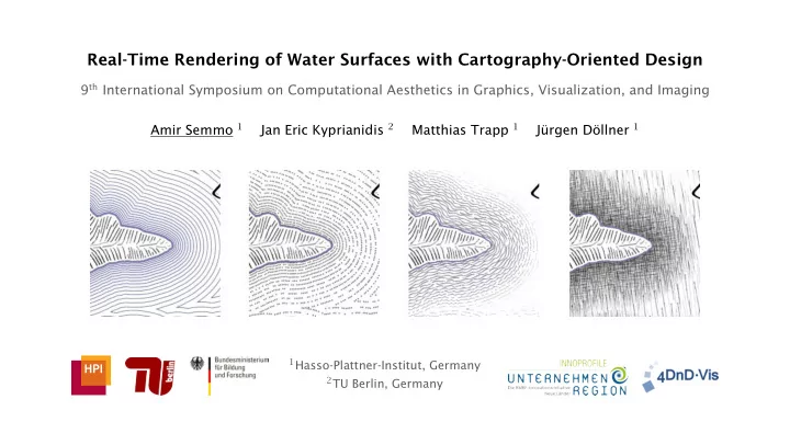
Real-Time Rendering of Water Surfaces with Cartography-Oriented Design
9th International Symposium on Computational Aesthetics in Graphics, Visualization, and Imaging Amir Semmo 1 Jan Eric Kyprianidis 2 Matthias Trapp 1 Jürgen Döllner 1
1Hasso-Plattner-Institut, Germany 2TU Berlin, Germany