
SLIDE 1
ProtoDUNE dual-phase overview
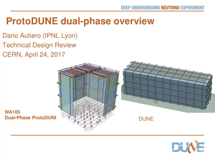
Dario Autiero (IPNL Lyon) Technical Design Review CERN, April 24, 2017
WA105 Dual-Phase ProtoDUNE
ProtoDUNE dual-phase overview Dario Autiero (IPNL Lyon) Technical - - PowerPoint PPT Presentation
ProtoDUNE dual-phase overview Dario Autiero (IPNL Lyon) Technical Design Review CERN, April 24, 2017 WA105 Dual-Phase ProtoDUNE DUNE Double-phase readout: Long drift, high S/N: extraction of electrons from the liquid and multiplication with
WA105 Dual-Phase ProtoDUNE
2
Long drift, high S/N: extraction of electrons from the liquid and multiplication with avalanches in pure argon with micro-pattern detectors like LEM (Large Electron Multipliers) Tunable gain (~20 minimum), two symmetric collection views, coupling to cold electronics
Anode 0V Grid 2 mm 1 cm LAr GAr LEM (1mm) 25-35 kV/cm
500 um holes 800 um pitch
3
rings
chimneys
chimneys
channels
Segmented anode in gas phase with dual phase amplification
X and Y charge collection strips 3.125 mm pitch, 3 m long 7680 readout channels
Drift coordinate 6 m = 4 ms sampling 2.5 MHz (400 ns), 12 bits 10000 samples per drift window
Prompt UV light
dE/dx ionization
Photomultipliers
Event size: drift window of 7680 channels x 10000 samples ⇒ 146.8 MB
4
5
TDR submitted on 31st March 2014 CERN-SPSC-2014-013 SPSC-TDR-004(2014) 2015 Annual SPSC progress report 31st March 2015 SPSC-SR-158 WA105 project MOU fully signed, December 2015
Project started in 2013 (CERN RB approval) following the submission
Collaborators from 10 countries and 22 institutes 5
Integration in DUNE project as DP-ProtoDUNE December 2015; EOI call for ProtoDUNEs, January 2016 2016 Annual SPSC progress report, April 7th 2016 CERN-SPSC-2016-017 SPSC-SR-184 DUNE CDR, July 2015: WA105 and Dual-phase 10 kton design LBNC review June 2016, LBNC review October 2016 2017 Annual SPSC progress report, April 4th 2017 CERN-SPSC-2017-011 SPSC-SR-206
7
Fully engineered versions of many detector components with pre- production and direct implementation (installation details and ancillary services) First overview of the complete system integration: set up full chains for QA, construction, installation, commissioning Anticipate legal and practical aspects related to procurement, costs and schedule verification Retirement of several risks for PD-DP thanks to (1) identification of critical components (2) early detection of potential problems
9
commissioning
performed by middle of February.
to start filling with LAr when a cold spot of ice appeared in a corner of the cryostat
Access on 14/3 No leaks: defects in insulation Cryostat purging restarted on 5/4, cool-down stopped again on 15/4 due to appearance of new cold spots
10
11
Full 3D electrostatic simulations completed for HV feedthrough, field-cage, cathode, ground grid
12
13
Invar frame + decoupling mechanisms in assembly in order to ensure planarity conditions +-0.5 mm (gravity, temperature gradient)
ensure minimal dead space in between CRPs CRP mechanical structure design: campaign of cold bath tests + photogrammetry
design of decoupling mechanism
14
Integration of the grid of submerged extraction wires in the frame minimizing dead space in between CRPs. Tests for the wires system design Thermal decoupling supports of G10 frame on invar frame Tooling, assembly and installation procedures defined getting ready for production CRP assembly animation: https://youtu.be/jcnJjlU-Cyc
Suspension feedthroughs
15
Field cage shares common basic structural elements (extruded profiles and FRP beams) with the single-phase ProtoDUNE Assembled in 8 vertical modules of 6238x3017 mm (2 modules per detector face). Each module is assembled out of 3 sub-modules
Sub-module 1 33 profiles Sub-module 2 33 profiles Sub-module 3 32 profiles + cathode
Continuity at center and borders (bent at 45 degrees) with clipping profiles Test setup at CERN for clips and electrical elements 98 profiles/module with 60 mm pitch Detailed electrostatic simulations performed for profiles/clips
being finalized
16
Transparent cathode with ITO (Indium-Tin-Oxyde) resistive coating on two sides of PMMA plates + TPB deposition at the top side:
structure completed
(produced by industry) chosen size 650x650x10 mm3
LBNC meeting of October 2016: PMMA cathode, despite all successful R&D, introduces many elements
which will not be retired by the 3x1x1 operation decided to reactivate the baseline design of the cathode, based on a mesh of pipes (extensively studied in the LAGUNA-LBNO DS and WA105 TDR) Minimal changes to the structure made for PMMA inserting 20 mm SS pipes with 105 cm pitch, completion of executive design, full simulations showing E<30 kV/cm
Cathode in 4 modules Ground grid above the PMTs, 2mm wires embedded in a SS frame 40/20 mm pipes, assembled in 4 modules
17
Preparation for PMTs installation:
warm/cold
Cathode HV system:
Heinzinger
to work up to 300 kV (300 kV milestone achieved in September in dedicated test setup, article: C. Cantini et al 2017 JINST 12 P03021.) Cryostat for test in batches of 10 PMTs (April 2017) Mechanical supports for installation on the cryostat floor in between corrugations (arrangement compatible with cryo-piping)
18
performed as well as precise definition of mounting operations
transportation boxes defined to be compatible with 10 kton assembly at LBNF
20 20
21
by Icarus, freed on April 7th in
activities
should become available in June to start the detector installation activities
started Schedule revision including:
infrastructure
cage, cathode) related to a more precise definition of the construction and assembly procedures
the 3x1x1
end of detector installation 6 April 2018 Overall close coordination among EHN1 and two ProtoDUNES needed during assembly (as recommended by SPSC)
start the detector installation 1/6/2017
Dedicated assembly/installation WG in strict contact with neutrino platform people
22
Integration of beam-line DAQ within WA105 White-Rabbit time distribution system Construction started looking forward to commissioning
Tertiary beam on H2 beamline: 1-12 GeV/c, momentum bite 5% (can be reduced to 1% with integrated spectrometer measurements)
kaons, protons + electrons contamination at low energies
O(100 M beam triggers to be acquired in 2018 in 120 days of beam operation) Beam instrumentation well defined by B.I. WG (beam profile monitors and trigger tiles TOF, 2 Cerenkov) Beam line with all instrumentation integrated
23
Momentum (GeV/c) / Particle e π K p 0.4 - 3.0 C1 CO2 @ 1bar TOF TOF 3.0 - 5 C1 CO2 @ 1bar C2 CO2 @ 3.5 bar No C2 No C2 5.0 - 12.0 C1 CO2 @ 1bar C2 CO2 @ <= 14bar No C1 No C2
16ch externally accessible:
chimneys
Short cables capacitance, low noise at low T
12 uTCA crates, 10 AMC cards/crate, 64 ch/card 24
ASICs 16 ch. (CMOS 0.35 um)
Full accessibility provided by the double-phase charge readout at the top of the detector
uTCA crate Signal chimney CRP Warm Cold FE cards mounted
blades
25
Ongoing R&D since 2006 in production for 6x6x6 (7680 readout channels) ASIC (CMOS 0.35 um) 16 ch. amplifiers working at ~110 K to profit from minimal noise conditions:
accessible from outside
6x6x6)
DAQ in warm zone on the tank deck:
emulated in low cost FPGAs (NIOS)
and high computing power in FPGAs
2015, pre-batch already deployed on 3x1x1
ASIC 16 ch. CMOS 0.35um
26
uTCA 64 channels AMC digitization cards (2.5- 25 MHz, 12 bits output, 10 GbE connectivity
(main components purchased last year ADCs,FPGAs,IDT memories …)
27
28
31
C.R. stands for Counting Room
Online processing and storage facility: internal bandwidth 20 GB/s, 1 PB storage, 384 cores: key element for online analysis (removal of cosmics, purity, gain, events filtering)
35 35
37
and costs assessment of most of the components for the 6x6x6 and to anticipate legal and procurement problems. The 3x1x1 assembly was completed in the fall 2016. The operation with liquid argon of the 3x1x1 has unfortunately not started yet due to delay in the cryogenic system and a recent problem with the cryostat.
measurements, FE electronics, noise and grounding, smooth operation of the DAQ system and online storage and processing commissioning has been conformal to expectations and very fruitful. The 3x1x1 activities have allowed retiring and/or reducing risks for PD-DP through (1) identification of potential critical components (2) early detection of potential problems. Most have been already taken into account in the 6x6x6 design.
completed by the end of November 2016. The schedule has been revised by taking into account final design and precise operation sequences, availability of infrastructure (clean room in 185 and cryostat + clean room buffer) , experience from 3x1x1 assembly, follow up of orders and tendering.
Cosmic Ray Triggers were already in production phase. The beamline + instrumentation design was completed as well and installation started. A global picture of the progress during the last year is described in the CERN SPSC 2017 yearly report
activities/experience with the 3x1x1. We are looking forward to the completion of the DP ProtoDUNE detector assembly in the cryostat and the exploitation with the beamline in 2018 !
38
39
assembly in parallel)
TCO = Temporary Construction Opening