
SLIDE 1
Preliminary Tests for Fuel Clad Behavior under LOCA using Multi Physics Coupled Experimental Facility ICARUS
Jongrok Kim, Jae Bong Lee, Hyeokjun Byeon, Kihwan Kim, Hae Seob Choi, Jong-Kuk Park, Young-Jung Youn, Sang-Ki Moon Korea Atomic Energy Research Institute, Daedeok-Daero 989-111, Yuseong-Gu, Daejeon, Republic of Koera
*Corresponding author: jongrok@kaeri.re.kr
- 1. Introduction
A safety criteria and licensing of nuclear power plant are changing because of the adaptation of the design extended condition (DEC) and high burn-up fuel safety
- issues. For this movement, multi-physics coupled safety
analysis has been required. One of activities related to multi-physics coupled safety analysis is a development
- f coupled safety analysis code system for the thermal
hydraulic safety analysis code and thermal mechanical safety analysis code. Currently, the experimental data to validate the coupled safety code system is not enough. Therefore, coupled experiments for thermal hydraulics and thermal mechanics are required to support this activity and to assess new safety criteria. An experimental facility named ICARUS (Integrated and Coupled Analysis of Reflood Using fuel Simulator) was developed for multi-physics coupled phenomena during loss of coolant accident (LOCA) at KAERI (Korea Atomic Energy Research Institute) [1-2]. Fig. 1 shows picture of ICARUS. This facility can simulate deformation of fuel cladding under LOCA and reflood
- condition. There were several previous experimental
research for this topic [3]. However, most previous facilities measured cladding geometry after end of test. So, the important design concept of ICARUS was to measure the thermal hydraulic and thermal mechanic parameters in real time during transient test. For this aim, several measuring systems to measure parameters related to thermal hydraulics and thermal mechanics were installed. These systems measure temperature, pressure and cladding geometry in real time during a transient experiment. Detail information
- f
measurement system is described in a reference [4].
- Fig. 1. Picture of ICARUS
In this paper, two preliminary experimental results for cladding ballooning and burst using ICARUS are presented and discussed.
- 2. Experimental Facility
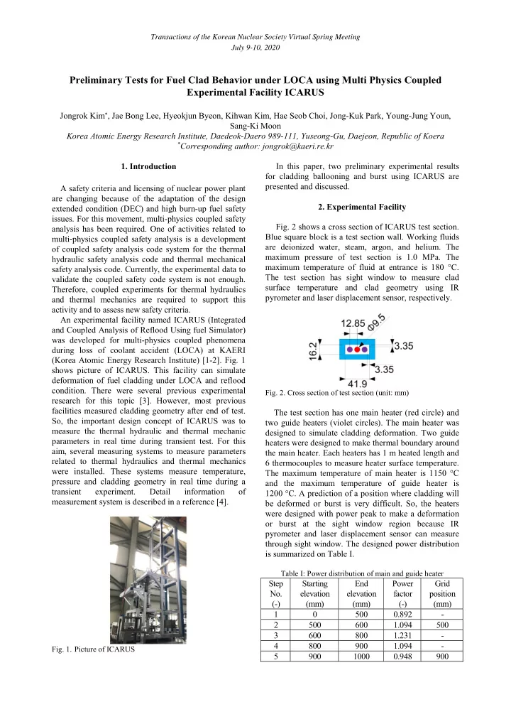
- Fig. 2 shows a cross section of ICARUS test section.
Blue square block is a test section wall. Working fluids are deionized water, steam, argon, and helium. The maximum pressure of test section is 1.0 MPa. The maximum temperature of fluid at entrance is 180 °C. The test section has sight window to measure clad surface temperature and clad geometry using IR pyrometer and laser displacement sensor, respectively.
- Fig. 2. Cross section of test section (unit: mm)
The test section has one main heater (red circle) and two guide heaters (violet circles). The main heater was designed to simulate cladding deformation. Two guide heaters were designed to make thermal boundary around the main heater. Each heaters has 1 m heated length and 6 thermocouples to measure heater surface temperature. The maximum temperature of main heater is 1150 °C and the maximum temperature of guide heater is 1200 °C. A prediction of a position where cladding will be deformed or burst is very difficult. So, the heaters were designed with power peak to make a deformation
- r burst at the sight window region because IR
pyrometer and laser displacement sensor can measure through sight window. The designed power distribution is summarized on Table I.
Table I: Power distribution of main and guide heater
Step No. (-) Starting elevation (mm) End elevation (mm) Power factor (-) Grid position (mm) 1 500 0.892
- 2
500 600 1.094 500 3 600 800 1.231
- 4
800 900 1.094
- 5