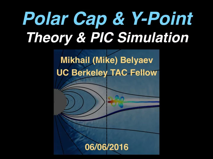

Polar Cap & Y-Point Theory & PIC Simulation Mikhail (Mike) Belyaev UC Berkeley TAC Fellow 06/06/2016
Theoretical Background We need to go beyond force- free to understand the emission and connect to observations! Magnetosphere approximated as force- free due to a high plasma density. ρ E + c − 1 J × B = 0 = ⇒ E · B = 0 B 2 − E 2 > 0 = ⇒ V d = c E × B /B 2 Spitkovsky (2006) Ω µ Emission in the Gaps magnetosphere requires E · B 6 = 0 non-force-free effects. ∂ u ∂ t + c Instabilities 4 π r · ( E × B ) = − E · J Current sheets B 2 − E 2 < 0
Part I: Polar Cap Goals: • Analytically determine distribution of current over the polar cap for a force-free magnetosphere with aligned spin and magnetic axes. • Relate spatial distribution of current to spatial distribution of polar cap pair production. Results: • Pair production occurs at the inner and outer edges of the polar cap when general-relativity taken into account. • No pair production at mid-latitudes on polar cap for simple surface field structure (e.g. dipole).
Polar Cap Pair Production J µ J µ ≡ − ( ρ c ) 2 + J 2 = γ − B pair production Pairs generated when there is backflow Pairs produced locally: of particles onto the polar cap. Field line by field line basis Beloborodov (2008) Timokhin & Arons (2013) ⇢ r / ρ GJ > 0 : no pairs J · ˆ J µ J µ < 0 r / ρ GJ < 0 : pairs J · ˆ J µ J µ > 0 : pairs
General Solution Method light cylinder Density is determined locally as GJ density B P polar cap J P Current is set by global magnetospheric structure Poloidal current flows along magnetic flux surfaces J P × B P = 0 flux surface invariant α J P ∝ B P Spitkovsky (2006) Trace back current on open B field lines from beyond light cylinder (simple current distribution) to the polar cap (complicated distribution)
Dipole: Computational Results Difference between GR R lc /r ∗ = 10 Kerr metric and flat ST due exclusively r s /r ∗ = . 5 to frame dragging. pair production no pair production PP With GR, two PP regions. Second region due to distributed return current. Flat ST No PP region always exists, because poloidal current changes sign. Belyaev & Parfrey (2016)
Dipole: Analytical Results • Gray curves — split monopole • Color curves — SM + 1st correction • Different linetypes — different amounts of open flux and different ratios of R_lc/r_*. Belyaev & Parfrey (2016) Tchekhovskoy, Philippov & Spitkovsky (2016) Gralla, Lupsascu, Philippov (2016)
More General Surface Field Extension to 3D Quadrupole+Dipole Bai & Spitkovsky (2010) Arons (1979) Gruzinov (2005) � � ˆ SM < ˆ b 2 b 2 � � z z � � P C timelike Current-like 3D vector invariant � � ˆ SM > ˆ b 2 b 2 � � along magnetic field lines. z z � � P C spacelike
Part II: Pulsar Y-Point Goals: • Understand particle trajectories at the Y-point and in the current sheet beyond it. • Understand dissipation at the pulsar Y-point, i.e. the role of pair multiplicity on dissipation and kink instability. Results: • Axisymmetric magnetosphere is inherently dissipative. • Y-point can extend inside light cylinder with PIC due to finite Larmor radius effect. • Radiation reaction likely to be important for particle trajectories at the Y-point.
Magnetospheric Current PP Open BP Model Field lines
Mind the Gap! Hollow Cone Emission? BP PP model has a large outer gap above the current sheet.
Luminosity & Dissipation Total energy flux Poynting flux r · S = − E · J Particle energy flux Dashed — BP model Solid — open field line PP
Positron Trajectory E Drift velocity close to speed of light near Y-point: B 0 v D, φ = − E r /B z . c, z = B z / γ D Particles in closed region accelerate radially across field lines (voltage drop). They cross light cylinder before turning around and escape to infinity in current sheet.
Electron Trajectory Electrons entering current sheet are sent back towards Y-point —> current sheet mostly positive charges Backflowing electrons cannot cross Y-point due to magnetic mirror effect. With radiation reaction it should be possible for electrons to flow back through Y-point.
Y-Point at Higher Pair Multiplicity current sheet thinner at higher multiplicity Kink more prominent at higher multiplicity
Current Sheet Kink Instability
Dissipation due to Kink smaller voltage drop at Y-point …but now extra dissipation due to kink! ( n + + n − ) / | n + − n − | ∼ 20 ( n + + n − ) / | n + − n − | ∼ 10
Conclusions 1. Targeted studies of polar cap and Y-point beyond force-free limit. 2. Polar cap — computed spatial distribution of pair production with implications for radio & high energy emission as well as for gaps. 3. Y-point — studying particle trajectories and dissipation. Around 20% of FF luminosity dissipated in current sheet. Dissipation is inherent to aligned rotator.
Recommend
More recommend