
SLIDE 1
Plastic Hose Forming System The Team Hashem Behbehani ME Walter - - PowerPoint PPT Presentation
Plastic Hose Forming System The Team Hashem Behbehani ME Walter Evans IV ME Ian Wogan ME Lauren Fandl ME The Team Continued.. Sponsor: Contact: Todd LaPant Mike Larocco Joseph Baldi Advisor: Dr. Joe Greene About Transfer
Must Do Should Do Would Be Nice Verify thermoforming process for tubes Short set up time Form all three types of hose Be versatile (accommodate multiple shapes) Fit in small area Complete work center Be operated by an unskilled laborer Forms hose quickly Form at least on of the three types of hose Repeatable Be controlled by PC Reliable Be cost effective
Requirements Engineering Specifications Metric Method/Device Target Conditions Short set-up time Time Minutes to setup Stop watch <5 minutes Unskilled laborer Fit in small area Area Feet squared Tape Measurer 10'x15' Includes the entire workstation Forms hoses quickly Units/Time Units/ hour Count units with stopwatch 60 hoses per hour From start to finish Repeatable Tolerances for Key Product Characteristics (KPC) Inches Checking Fixture ±2 variation of bend angle Includes all hoses formed Reliable Mean Time between Failures Weeks Endurance Test 1000 hoses Under normal factory conditions Cost effective Money US Dollars Cost Analysis <current cost Operational costs
to temperature change
Hose Tmelt Tmalleable
Can hose be formed? Markel 165 °C/ 329°F 125-145 °C/ 257-293 °F Yes Cooper Standard 155 °C/ 311 °F 100-125 °C / 212-257 °F Yes Kongsberg N/A N/A No
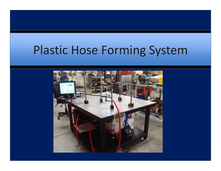
– work table and fixturing system
– heating loop – cooling loop – Control System
resources at Transfer Flow Inc.
welded to steel tubing
fixturing system using magnetic bases Positioning Arm and Corner Fixtures
The process must be versatile
Setup for a new hose shape:
set the positioning arms in the correct locations
Consists of: – High temperature pump – Insulated hot reservoir – Immersion heater – Adjustable flow control valve – High temperature solenoid valve Operation Conditions: – Kept under pressure to prevent the propylene glycol from vaporizing – Propylene glycol heated to 250 degrees Fahrenheit – Flow rate of 2.1 gallons per minute
Consists of: – Pump – Cold reservoir – Adjustable flow control valve – Solenoid valve Operation Conditions:
Insert Video Here Talk about operation of the machine: Heating Cycle Operation: Turn the pump on Heat the hose Turn off the pump Purge hose with pressurized air, returning all heated propylene glycol to the hot reservoir. Cooling Cycle Operation: Turn the pump on Cool the hose Turn off the pump Purge hose with pressurized air, returning all cool propylene glycol to the cold reservoir.
Must Do Should Do Would Be Nice Standard operation module Maintenance module Debugging Module Display/Store data from sensors Maintenance log Override/Force Step Emergency shutdown protocol Leak Detection Protocol Adjust System Variables Easy to read dialogue boxes and menus
Stop Button Coalescing Air Filter Emergency Pressure Release Valve Signage
Fabricated Design Original Design
– Uses statistical methods to improve the quality of manufactured goods – Used to optimized parameters prior to performing test plan
Determine the Factors Determine the Factors Design the Matrix Experiment Design the Matrix Experiment Define the Data Analysis Experiment Define the Data Analysis Experiment Conduct the Experiment Conduct the Experiment Data Analysis Predict the Impact of the Design Factors Validation Experiment (Test Plan)
as our test data
parameters
Requirement Target Value Set- up Time ≤ 5 minutes Machine Footprint ≤ 150 square feet Repeatability ± 2σ variation Cycle Time per Hose ≤ 1 minute
– Transfer flow personnel
– California State University, Chico personnel
Total Budget Cost Purchased Parts 4,128.04 Raw Materials 360.00 Fall Semester Time (hours) Cost/Hour Benefit and Overhead Factor Engineering Time 525.5 36.54 1.77 33,987.13 Labor and Machining 40 30.00 1.77 2,124.00 Spring Semester Time (hours) Cost/Hour Benefit and Overhead Factor Engineering Time 626.5 36.54 1.77 40,519.39 Labor and Machining 78 30.00 1.77 4,141.80 Estimated Total Cost: 85,260.36
Engineering Specifications Target (for Quantitative) Target Met? Must Do: Verify a thermoforming process Yes Be Versatile Yes Operated by an unskilled Laborer Yes Form at least one type of hose Yes Controlled by PC Yes Cost Effective TBD Should Do: Short set-up time ≤ 5 min TBD Fit in a small area ≤ 150 feet squared Yes Cycle time per hose ≤ 1min No Repeatable ± 2 σ TBD Reliable 1000 hoses (MTBF) TBD Would be Nice: Form all three types of hose No Complete work center Yes
– Heat transfer to cold tank
– Example:
– Heat sinks
– Hot tank fluid agitation – Thermocouple placement – Distribution manifold size
– Shielding on table – Eyewash station for hot fluid (OSHA: Title 8) – Work station hoses rated to a higher pressure – Quick connect fittings – Pressure check system – Air filtration system
Control System Fixturing System Distribution Manifold Fluid Reservoir Motor Pump