Physics 116 Lecture 17 Refraction and lenses Oct 27, 2010 R. J. - - PowerPoint PPT Presentation

physics 116 lecture 17 refraction and lenses
SMART_READER_LITE
LIVE PREVIEW

Physics 116 Lecture 17 Refraction and lenses Oct 27, 2010 R. J. - - PowerPoint PPT Presentation

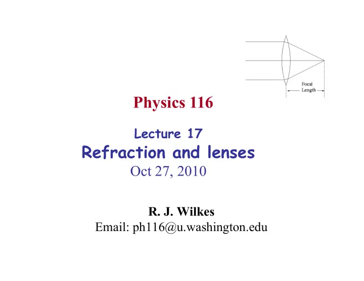
Physics 116 Lecture 17 Refraction and lenses Oct 27, 2010 R. J. Wilkes Email: ph116@u.washington.edu Lecture Schedule (up to exam 2) Today 2 Simple case: Refraction at a plane surface Last time: Light bends at interface between


slide-1
SLIDE 1
  • R. J. Wilkes

Email: ph116@u.washington.edu

Physics 116

Lecture 17

Refraction and lenses

Oct 27, 2010

slide-2
SLIDE 2

2

Today

Lecture Schedule

(up to exam 2)

slide-3
SLIDE 3

3

Simple case: Refraction at a plane surface

  • Light bends at interface between refractive indices

– bends more the larger the difference in refractive index – can be effectively viewed as a “least time” behavior

  • get from A to B faster if you spend less time in the slow medium

– Object at B appears to be at location B’

  • Fish in tank appears to be displaced
  • Put your feet in the lake and they seem bent

n2 = 1.5 n1 = 1.0 A B 1 2 Exact formula: n1sin1 = n2sin2 B’

Last time:

slide-4
SLIDE 4
  • In a thick piece of glass (n = 1.5), the light paths are as shown

– About 4% of light energy is reflected from the surface (mirrorlike)

  • Same thing happens at back surface (4% of that gets re-reflected

from the inside front surface, and ends up going out the far side also…)

n1 = 1.5 n2 = 1.0 n0 = 1.0

4

Reflections, and refractive optical illusion

incoming ray from object (100%) 4% ~ 4% 96% 92% transmitted 0.16% 8% reflected in two reflections (front & back)

  • bject appears displaced

due to jog inside glass

Apparent direction to object

A B

slide-5
SLIDE 5

5

FYI: Fermat’s principle here too

  • Fermat’s Least-Time principle

– Pierre de Fermat, French mathematician, 1601-1665

  • Best known for “Fermat’s Last Theorem”
  • Wrote a friend just before he died “I have discovered a truly

remarkable proof which this margin is too small to contain” – but he never got to explain

  • F’s Last Theorem was finally proven true in 1994 (by A. Wiles,

Princeton U.)

Least-time principle applies to refraction also:

Actual path is quickest path, taking into account changes in light speed! Has solutions (Pythagoras) Never works, if N>2 But

slide-6
SLIDE 6

6

Underwater refraction: Total Internal Reflection

  • Looking up toward air from under water, refraction bends light

rays away from normal (going from higher to lower n)

  • For large angle of incidence, angle of refraction becomes >90° !

– thereafter, you get total internal reflection – for glass, the critical internal angle is 42°, for water, it’s 49° – a ray within the higher index medium cannot escape at greater incidence angles (look at sky from underwater…can’t see out!) – Same principle is used to confine light within optical fibers

n2 = 1.5 n1 = 1.0 42° At critical angle, refracted ray hugs surface At steeper angles, rays are 100% reflected Shallow-angle rays escape

slide-7
SLIDE 7

Polarization by reflection

  • David Brewster (1781-1868):

Found that when !T - !R = 90deg reflected light is polarized parallel to surface (perpendicular to plane of incidence) By Snell's Law: Brewster (polarizing) angle: e.g., air/glass has !B = tan -1(1.5)= 57deg Reason: – incident light has E components parallel and perpendicular to plane of incidence – reflected light can only have component perpendicular to plane of incidence for !R = !T + 90deg

  • Parallel component would have to be along propagation direction = longitudinal

wave! n1 n2

!T !R !I 90deg

slide-8
SLIDE 8

8

Refraction at curved surfaces: Lenses

  • Lenses = medium with higher n than air, with curved surfaces
  • Convex (positive or converging ) lens: thicker at center than edges

– Positive lens (by convention, we say its focal length f is positive) focuses parallel incoming rays to a point at distance f behind it

Lens with curved surfaces front and back (double-convex) bends light twice, each time refracting incoming ray towards normal line. Snell’s law of refraction applies at each surface. (One curved/one flat surface = plano-convex; inward cuving = concave lens) Focal length may be given in m or mm. Optometrists instead specify “refracting power” in diopters: higher power = shorter f F (in diopters) = 1/(f in meters) +1 diopter lens has f=1 m +2 diopter lens has f=1/2 m

slide-9
SLIDE 9

9

Diverging lenses

  • Concave (negative or diverging ) lens: thinner at center than

edges

– Negative lens (we say its f is negative) makes parallel incoming rays bend outwards, so it seems as if light were coming from a point in front of the lens (focal point)

  • Meniscus lens: has both sided curved in the same direction, but
  • ne surface is more sharply curved than the other

– Commonly used for eyeglasses – Can be either positive or negative (thicker at center, or thinner) f Meniscus lenses

Diverging (-) Converging (+)

Negative lens

slide-10
SLIDE 10

Ray tracing rules for lenses

Ray tracing rules for a (simple, thin) lens are: 1) Rays arriving parallel to the axis emerge to pass through the back focal point 2) Rays passing through the front focal point emerge parallel to the axis 3) Rays through center of the lens are undeviated

image

  • bject

f 3 2 1

  • Object distance

dO Image distance dI

Focal pt

This lens setup could be used as a camera, or a slide projector

  • Focal pt

Rays from object tip re-converge at a point, forming a real, inverted, magnified image there

slide-11
SLIDE 11

When object is close to converging lens

1) Rays arriving parallel to the axis emerge to pass through the back focal point 2) Rays through center of the lens are undeviated 3) Rays do not re-converge – image is virtual

image

  • bject

f 2 1

  • Object distance

dO Image distance dI

Focal pt

This lens setup could be used as a magnifying glass

  • Focal pt

Gazing through the lens toward the object, we see rays appearing to emerge from a virtual, erect, magnified image

slide-12
SLIDE 12

Diverging lens, distant object

1) Rays arriving parallel to the axis emerge as if they came from the focal point 2) Rays through center of the lens are undeviated 3) The intersection of these rays shows image location, orientation, and size

image

  • bject

f 2 1 Object distance dO Image distance dI

Focal pt

This lens could be used in eyeglasses for a nearsighted person

  • Gazing through the lens toward

the object, we see rays appearing to emerge from a virtual, erect, demagnified image that is closer than the object

slide-13
SLIDE 13

Diverging lens, nearby object

1) Rays arriving parallel to the axis emerge as if they came from the focal point 2) Rays through center of the lens are undeviated 3) The intersection of these rays shows image location, orientation, and size

image

  • bject

f 2 1 Object distance dO Image distance dI

Focal pt

  • Very little difference – image just

moves a bit closer to the lens

slide-14
SLIDE 14

Ray tracing applet – try it yourself

http://silver.neep.wisc.edu/~shock/tools/ray.html (original source http://webphysics.davidson.edu/Applets/Optics4/Intro.html)