Paint and Click: Unified Interactions for Image Boundaries B. Summa, - - PDF document

paint and click unified interactions for image boundaries
SMART_READER_LITE
LIVE PREVIEW

Paint and Click: Unified Interactions for Image Boundaries B. Summa, - - PDF document

DOI: 10.1111/cgf.12568 EUROGRAPHICS 2015 / O. Sorkine-Hornung and M. Wimmer Volume 34 ( 2015 ), Number 2 (Guest Editors) Paint and Click: Unified Interactions for Image Boundaries B. Summa, A. A. Gooch, G. Scorzelli, and V. Pascucci Scientific


slide-1
SLIDE 1

EUROGRAPHICS 2015 / O. Sorkine-Hornung and M. Wimmer (Guest Editors) Volume 34 (2015), Number 2

Paint and Click: Unified Interactions for Image Boundaries

  • B. Summa, A. A. Gooch, G. Scorzelli, and V. Pascucci

Scientific Computing and Imaging Institute & The University of Utah

(b) (a) (c) (d) (e)

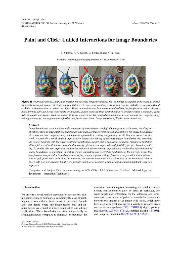
Figure 1: We provide a novel, unified interaction for pairwise image boundaries that combines both paint and constraint-based user edits. (a) Input image. (b) Desired segmentation. (c) Using only painting edits, a user can use include (green striped) and exclude (red) annotations to select the object. These annotations can be numerous and tedious for fine features such as the legs and antennae. (d) Using only constraints (or anchors), a user can click (red) control points to form the object’s boundary. Even with automatic constraints (yellow), many clicks are required. (e) Our unified approach allows users to mix the complementary editing metaphors, leading to a more flexible and faster experience. Image courtesy of Flicker user tonrulkens. Abstract Image boundaries are a fundamental component of many interactive digital photography techniques, enabling ap- plications such as segmentation, panoramas, and seamless image composition. Interactions for image boundaries

  • ften rely on two complementary but separate approaches: editing via painting or clicking constraints. In this

work, we provide a novel, unified approach for interactive editing of pairwise image boundaries that combines the ease of painting with the direct control of constraints. Rather than a sequential coupling, this new formulation allows full use of both interactions simultaneously, giving users unprecedented flexibility for fast boundary edit-

  • ing. To enable this new approach, we provide technical advancements. In particular, we detail a reformulation of

image boundaries as a problem of finding cycles, expanding and correcting limitations of the previous work. Our new formulation provides boundary solutions for painted regions with performance on par with state-of-the-art specialized, paint-only techniques. In addition, we provide instantaneous exploration of the boundary solution space with user constraints. Finally, we provide examples of common graphics applications impacted by our new approach. Categories and Subject Descriptors (according to ACM CCS): I.3.6 [Computer Graphics]: Methodology and Techniques—Interaction Techniques

  • 1. Introduction

We provide a novel, unified approach for interactively edit- ing pairwise image boundaries, combining the ease of paint- ing interactions with the direct control of constraints. Bound- aries that define where one image region ends and an-

  • ther begins are crucial in image composition and editing
  • applications. These boundaries are often automatically or

semiautomatically computed to minimize or maximize the transition between regions, removing the need to metic- ulously edit boundaries pixel by pixel. In particular, our work targets user interaction for the automatic and semi- automatic construction of pairwise boundaries (boundaries between two images or an image with itself), which have been used with great success for a variety of research areas such as texture synthesis [EF01, CSHD03], digital panora- mas [Dav98,LZPW04,STP12], seamless pasting [JSTS06], and image segmentation [MB95,MB98,LSTS04].

c 2015 The Author(s) Computer Graphics Forum c 2015 The Eurographics Association and John Wiley & Sons Ltd. Published by John Wiley & Sons Ltd.

DOI: 10.1111/cgf.12568

slide-2
SLIDE 2
  • B. Summa, A. A. Gooch, G. Scorzelli, & V. Pascucci / Paint and Click: Unified Interactions for Image Boundaries

User interaction for image boundaries often takes one of two forms, defined by the underlying core algorithm. First, minimum cut approaches allow users to edit boundaries by painting and, second, minimum path approaches allow users to edit boundaries by the creation and manipulation of con-

  • straints. Figure 1c illustrates Adobe Photoshop’s quick se-

lection painting interactions being used to select the beetle of Figure 1a; similar interactions are often used for minimum cut implementations. Selecting the beetle requires over 30 interactions, which are most challenging in areas with fine features, such as the antennae and legs. These features re- quire a user to carefully trace their interior and/or exterior, which can be tedious and error-prone. Figure 1d illustrates adding constraints via Photoshop’s magnetic lasso tool, an approach similar to most minimum path implementations. Red constraints are user clicks and yellow constraints are automatically added by the software. For areas such as the beetle’s body in Figure 1d, the amount of points needed to be added by the user can be excessive and the interaction pro- cess slow. As the example in Figure 1 illustrates, the benefits and drawbacks of the two approaches are often complemen-

  • tary. For example, the antennae that need tedious painting

require only a small number of user constraints and the la- borious constraints on the beetle’s body are easily avoided with a simple painting annotation. The complementary nature of painting and constraints speaks to the need for a unified approach to image bound-

  • aries. For ease of implementation, most methods support

painting and constraint schemes independently. After com- puting a boundary for a given interaction scheme (painting

  • r constraints), the boundary is finalized and the paintings
  • r constraints are discarded. Such a step-by-step pipeline

leads to new edits overruling previous edits. As shown in our companion video, successive painting may remove a well- placed boundary formed by constraints or a previous paint-

  • ing. Painting and constraints, working together in a single

approach, lead to fewer interactions overall. For example, an initial coarse painting of the beetle’s body reduces the con- straints needed to select its legs to just a few clicks, since the

  • peration moves only an already semioptimal boundary.

Our unified technique provides users with the ability to mix interactions and choose the interaction that best fits their current task without loss of previous edits. As supplemental material, we provide video captures of our new approach, which reduces the time to select the beetle in Figure 1 by almost half when comparing our unoptimized research code to pure constraints and painting with Photoshop. Even when compared to combining both interactions independently, our new approach improves editing time significantly. In this paper, we detail our new, unified approach for im- age boundaries, describe how to compute boundaries effi- ciently, and provide example image processing applications. Several technical innovations were necessary to achieve our

  • approach. In particular, the contributions of this paper are:
  • Robust formulation of the optimal boundary problem

guaranteed to find the minimum boundary;

  • Fast & parallel algorithm to find the minimum boundary;
  • Novel extension of our boundary mechanics allowing

users to add constraints to the minimum boundary with instant feedback;

  • Strategy to combine independent minimum boundaries

that allows users intuitive editing with multiple painting annotations;

  • Practical applications for our new unified approach.
  • 2. Related Work

Given its fundamental use in image processing, the auto- matic computation of image boundaries has an extensive body of work. Below, we concentrate on how interaction has been used to aid automatic solutions or provide boundary solutions semiautomatically. Painting Interaction. Minimum cut algorithms, such as Graph Cuts [BVZ01,BK04,KZ04], compute boundaries via an optimization often with a user’s initial painted anno- tations as input. A painting interaction [RKB04, LSTS04, LSGX05, JSTS06, NFK07, WAC07, VN08, AP08, XLJ∗09, XYJ13, LSS09, LS10, TGVB13] has the benefit of a metaphor (include and exclude painting) easily understood by most users. Paint-based interactions provide a user with quick manipulations, but are often only a front-end to an ex- pensive, iterative optimization. Additional annotations and edits result in a full solution recomputation, which can be time consuming over many edits. Even if a solution can be produced quickly, more annotations may be required to re- solve ambiguous boundaries [LSTS04], an ill-defined en- ergy specification, or places where multiple aesthetically valid solutions are possible [STP12]. The previous work of Li et al. [LSTS04] has shown the need for constraints in painting-based approaches for resolving boundary ambigui-

  • ties. With fine features, the additional careful annotation can

be tedious and require almost the same effort as the manual editing of the image masks. Our work provides a fast and robust algorithm for painting interactions with constraints. Constraint Interaction. Interaction using minimum paths and constraints, first seen in Mortensen and Barrett [MB95, MB98], involves the computation of minimum path trees from user-defined points (constraints). Adding new con- straints simply requires a traversal of the precomputed

  • trees. Accordingly, the minimum boundary with the given

constraints can be provided instantly and the constraints can be manipulated interactively. Recent work on panora- mas [STP12] uses a variation on this approach to combine the ease of an automatic solution along with the direct, semi- automatic editing of the boundary. The previous work is lim- ited to panoramas, since it assumes that the overlaps are small and that each image has unique areas outside the over-

  • lap. Therefore the technique of Summa et al. [STP12] is

incapable of handling inset images. Our constraint interac-

c 2015 The Author(s) Computer Graphics Forum c 2015 The Eurographics Association and John Wiley & Sons Ltd.

386

slide-3
SLIDE 3
  • B. Summa, A. A. Gooch, G. Scorzelli, & V. Pascucci / Paint and Click: Unified Interactions for Image Boundaries

(a) (b) (c) C C

Figure 2: (a) Input image. (b) Drag-and-Drop Past- ing [JSTS06] boundary solution fails to properly find the dancer’s left leg (inset), due to minimum distance separat- ing cut (red). (c) Our minimum energy separating path (red) is guaranteed to find the minimum boundary. Image courtesy

  • f Richard Calmes Photography.

tion approach achieves the Summa et al. ease of use without limitations and their supported cases are simply a subset of the cases handled by our work. Lazy Snapping [LSTS04] provides a polyline approximation of an automatically com- puted boundary for a user to adjust. After edits, additional automatic solutions are produced, guided by edited polyline. In contrast, a user can interactively explore the boundary so- lution space with our approach without the need for addi- tional optimizations or approximations.

  • 3. Paint and Click

The core of our algorithm consists of painting annotations, finding the minimum cycle, and the addition of constraints. Painting Annotation: To compute boundaries for an im- age, the user begins by labeling the pixels to include and/or exclude from the selection via a painting metaphor. Multi- ple, coincident, “like” painting strokes are computed as a single annotation. Similar to other boundary techniques, at least one annotation must be defined; otherwise the bound- ary problem is ill posed. Our base algorithm assumes that each annotation is independent and therefore, for the remain- der of this section, we discuss solutions for a single annota-

  • tion. In Section 3.4, we show how to intuitively combine the

independent solutions. Minimum Cycle: Our algorithm finds the minimum closed path that optimally separates the annotated pixels from the rest of the input. We refer to this path as our minimum cy-

  • cle. Our technique differs in two ways from the previous

work [JSTS06]. (1) We provide a new solution to the mini- mum cycle calculation that is robust and guaranteed to find the minimum cycle. Figure 2 demonstrates where the previ-

  • us work fails to properly segment the dancer. (2) Our al-

gorithm has significantly less complexity than that of Jia et

  • al. [JSTS06]. Our complexity provides a practical improve-

ment of up to a 48 times speedup in our test data and allows

  • ur unified approach to be on par with the fastest paint-only

boundary technique [STC09]. Adding Constraints: Our approach for calculating the min- imum cycle enables the user to quickly and interactively add multiple constraints in order to refine the boundary while

A

(c) (a) (b)

B

Overlapping Images Overlap with Energy Annulus Annotation

O

Minimal Boundary

Figure 3: (a) A user annotation (green striped) for over- lapping images A and B. (b) and (c) O, the solution space, contains the boundary of overlap (blue) and the region an- notated by the user (green), and a minimum cycle (black). keeping it minimal. We perpetually stay one step ahead of the user with quick precalculations, thereby keeping all in- teractions fluid and instantaneous. The next three sections provide details on our algorithm and describe how our implementation enables a unified for-

  • mulation. Section 3.1 defines the parameters of our input and

basic definitions for the exposition of our technique. We de- tail how to compute the minimum cycle in Section 3.2 and how to easily and efficiently add interactive user constraints in Section 3.3. 3.1. Pairwise Boundaries For ease of explanation, we assume that two overlapping im- ages, A and B, serve as the input to our technique. In the case of object selection or foreground/background segmen- tation, A and B are the same image and the following for- mulation still applies. Given the two input images, we want to compute the pairwise boundary, boundaries between two images, or an image with itself, such that there is a discrete labeling L for all pixels in their overlap. The labeling deter- mines the image that contributes a pixel to the final compos- ite or the pixel that is selected. The labeling is defined as L(p) = {A,B} for location p in the overlap. Input for this procedure is typically an initial labeling provided by user annotations, another algorithm, or a partial overlap. For pur- poses of illustrating such labeling in this paper’s figures, all include annotations are shown in striped green and exclude annotations are shown in red. Each annotation can have a single component or multiple connected components The labeling can be computed by minimizing the transi- tion [ADA∗04], Et, between images based on a piecewise smoothness Es(p,q), where (p,q) ∈ N and N is the set of all neighboring pixels in the overlap. Et(L) =

(p,q)∈N

Es(p,q). The smoothness energy can vary based on the type of tran- sition required. For example, equations can minimize: Es(p,q) = IL(p)(p)−IL(q)(p)+IL(p)(q)−IL(q)(q).

  • r maximize the transition in pixel values:

Es(p,q) = e−I(p)−I(q) (1)

c 2015 The Author(s) Computer Graphics Forum c 2015 The Eurographics Association and John Wiley & Sons Ltd.

387

slide-4
SLIDE 4
  • B. Summa, A. A. Gooch, G. Scorzelli, & V. Pascucci / Paint and Click: Unified Interactions for Image Boundaries

when L(p) = L(q) and Es(p,q) = 0 otherwise. Given an initial labeling of the pixels, the problem is to find a new labeling that minimizes the transition between la-

  • bels. Towards enabling the minimization, we represent the

pixels as a planar, 4-neighborhood, energy-weighted pixel graph G = (V,E), where V are pixel locations in the over- lap and E are edges that connect pixel neighbors. Edges are weighted by the energy function Es. We chose 4 pixel neighborhood because 4-neighborhood minimum paths can

  • nly cross once. An 8 pixel neighborhood does not have the

same property, has lower performance, and a larger neigh- borhood search area was not necessary to produce high qual- ity boundaries. Most previous techniques produced a new minimal la- beling via minimum cut of the graph, such as in Li et

  • al. [LSTS04]. As this previous work has shown, mini-

mum cuts are insufficient for a fully unified technique since boundary edits require approximations and repetitive op-

  • timizations. In contrast, minimum paths have been shown

to provide user control of the boundary without approx- imations [MB95, MB98, STP12], resulting in a what you see is what you get (WYSWIG) interaction. In addition, Summa et al. [STP12] showed that a dual graph between pixels can be formed, on which the minimum path can pro- duce the same solution as a minimum cut. We overcome the deficiencies of minimum cut boundary interactions and the limitations of the open paths of previous minimum path work [MB95, MB98, STP12] by providing a unified ap- proach based on closed minimum paths. As an added benefit, minimum paths provides the option to operate and minimize on the boundary pixels themselves, an extremely useful operation for color correction applica-

  • tions. In particular, for seamless composition it is desirable

to minimize the pixel color difference on the boundary: Et(L) = ∑

p∈∂Li

IA(p)−IB(p), (2) where ∂Li is a set of points such that if p ∈ ∂Li then L(p) = i and L(q) = i for some q such that (p,q) ∈ N and i would correspond to the image that is to be seamlessly composed. We assume in our exposition that the minimum bound- aries occur on the pixels themselves. In other words, each boundary is a sequence of pixels (p1,..., pn) and the nodes

  • f our graph are the pixel locations with edges connecting

nodes corresponding to adjacent pixels. 3.2. Computing the Minimum Cycle For clarity in the illustrations in the paper, we describe the computation of the minimum cycle via the planar annulus, shown in Figure 3. A planar annulus represents the solution domain for a single annotation and is defined as the area be- tween two concentric boundaries. As shown in Figure 3c, the interior boundary (green) of the annulus represents the

(a) (b) (c) (d)

C

Figure 4: (a) Computation of a minimum cycle illustrated via a planar annulus. (b) The minimum separating path (red C) from interior (green) to exterior (blue) boundary nodes. (c) Compute the set of minimum paths from the separating path nodes to their replicated selves. The minimum path of the set is the minimum cycle (d) annotation boundary and the exterior boundary (blue) repre- sents the solution domain boundary. We will also describe a separating path, consisting of the pixels or nodes in the pixel graph that joins the interior and exterior boundaries. Our approach for computing the minimum cycle makes two major improvements to the work of Jia et al. [JSTS06], including a robust separating path for splitting the planar annulus defined by the boundaries and a lower complexity divide-and-conquer approach for generating an optimal min- imal cycle between the interior and exterior boundaries. Our method results in a fast computation and the correct minimal cycle, as we describe in the next subsection. 3.2.1. Robust Separation of the Domain In order to compute a minimum cycle between these bound- ary paths, we first create a separating path, C, that trav- els from the nodes of the exterior boundary to the interior boundary (Figure 4b). We then replicate the nodes of the separating path to split our solution domain. The minimum cycle is found via a search through the collection of all mini- mum paths from the separating path nodes, ni, to their repli- cated selves, n′

i [IS79,Rei83],

MinCycle = min

ni (MinPath(ni,n′ i)).

Figures 4c and d illustrate the search for a minimum cycle. In our work, we make a critical adjustment to the mini- mum distance cut technique used by Jia et al. [JSTS06]. In the previous work, the separating cut was based upon the minimum distance from the interior to the exterior of the an- nulus, which does not account for the underlying energy. Jia et al. assumed that a minimum boundary would not cross the separating cut more than once, a safe assumption for simple color correction boundaries. However, when this assump- tion does not hold, such as in the case of a more general image segmentation or object selection, their technique will not find the minimum boundary. As shown in Figure 2b, a minimum distance cut bisects one of the legs of the dancer. Therefore, any boundary produced using such a separating cut cannot trace the inside of this leg completely. As shown in Figure 4, we compute our separating path

c 2015 The Author(s) Computer Graphics Forum c 2015 The Eurographics Association and John Wiley & Sons Ltd.

388

slide-5
SLIDE 5
  • B. Summa, A. A. Gooch, G. Scorzelli, & V. Pascucci / Paint and Click: Unified Interactions for Image Boundaries

Level 0 Level 1

Figure 5: Divide and conquer strategy to find the minimum

  • cycle. First compute the cycle associated at the separating

path’s midpoint. Split the separating path at the midpoint. Recurse on the two subpaths. Partition recursion solution domain by the midpoint’s cycle and includes the cycle itself. Grey regions denote areas excluded from the computation. as the minimum path on the underlying energy, not dis- tance, between all nodes on the exterior boundary to the nodes on the interior boundary. The separating path can be computed by connecting the nodes of the exterior bound- ary with zero-weighted edges to a source dummy node and connecting all interior boundary nodes to a destina- tion dummy node. The separating path is then computed as the minimum path between the source and destination nodes [IS79,Rei83]. Since the separating path connects inte- rior and exterior boundaries, the minimum cycle must cross it once and only once [SGSP14]. 3.2.2. Zero Constraints – Divide and Conquer Additionally, our method improves upon the performance of the Jia et al. [JSTS06] boundary solution by introducing a new divide and conquer algorithm. Our algorithm reduces the runtime of our zero constraints solve from O(MN) to O(N log M) for integer energy [MB95,MB98] and O(MN log N) to O(N log N log M) for floating point energy [Dij59], where M is the length of the separating path and N is the number

  • f pixels in the annulus. The complexity improvement pro-

vides as high as a 48 times speedup in our test data. The complexity of the Jia et al. algorithm fits their desired of- fline boundary solution, but our goal is to produce image boundaries with interactive feedback. Moreover, the previ-

  • us work assumed the separating path length, M, is small,

an assumption that does not hold for our robust separating path in applications such as object selection. Our recursive binary divide and conquer strategy, moti- vated by the work of Reif [Rei83], exploits the fact that the minimum paths computed in finding the minimum cycle can be coincident but cannot cross [SGSP14]. Figure 5 illustrates a step of our recursive algorithm. First, the minimum path from the middle node of the current separating path is com- puted to its replicated self. The separating path then is split about the midpoint and the algorithm recurses on the two

  • subpaths. The solution domain in the binary recursion can

be partitioned by the midpoint’s minimum path with each partition including the path itself. 3.3. Adding Interactive User Constraints Our unified approach provides the ability to easily add user constraints since adding a single constraint is equivalent to finding the minimum cycle between the interior and exterior boundaries that must pass through a specific node. Adding additional constraints simply requires the examination of current constraints and their minimum path trees, as we ex- plain in the following subsections. 3.3.1. Single Constraints Adding a single constraint includes building clockwise (CW) and counterclockwise (CCW) minimum path trees for all separating path nodes, finding the minimum cy- cle through the constraint, and creating a separating path through the constraint as a preprocess for additional con- straints. For every node of the separating path, we compute the minimum path tree in both clockwise and counterclockwise

  • rientations with the node (or its replicated self) as the root.

See Figure 6a. Each tree can be encoded as a step-direction and cost buffer. The step-direction buffer encodes the direc- tion of a node’s parent in one byte whereas the cost buffer stores the minimum path cost for each node at a desired pre-

  • cision. This preprocess has a complexity of O(2NM).

We define the constraint-minimum cycle as the minimum cycle that must pass through the constraint(s). To find the constraint-minimum cycle, we find the oriented paths from a separating path node, ni, and its replicated self, n′

i, to the

constraint whose sum gives the minimum cost: MinCycle(c) = min

ni (MinPath(ni,c)+MinPath(n′ i,c)),

where c is the constraint location (Figures 6b, 6c, and 6d). The cost buffer can be dropped after computation by keeping track of the minimum cycle cost along with the index of the separating path node whose trees provide the cycle. After the initial constraint is positioned (Figure 6e), a min- imum path between the exterior and interior boundaries con- taining the constraint can be used to separate the annulus into a disk. We call this the constraint-separating path. As a preprocess to enable the addition of more constraints, two

  • riented minimum path trees (CW and CCW) with roots be-

ing the first constraint node and its replicated self (Figure 6f) are computed with a cost of O(2N). 3.3.2. Two or More Constraints Given the two oriented precomputed minimum path trees, finding the boundary with a second constraint is simply a tree traversal (Figure 6g). Additional constraints operate similarly, as illustrated in Figures 6h and 6i; after each con- straint is set, a similar preprocess of generating oriented trees

  • ccurs for the next constraint.

Constraints are stored in a circular array and are inserted

c 2015 The Author(s) Computer Graphics Forum c 2015 The Eurographics Association and John Wiley & Sons Ltd.

389

slide-6
SLIDE 6
  • B. Summa, A. A. Gooch, G. Scorzelli, & V. Pascucci / Paint and Click: Unified Interactions for Image Boundaries

...

(a) (b) (c) (d) (e) (f) (g) (h) (h) (i) C C W T r e e C W T r e e

Figure 6: User constraints. (a) Compute a CW and CCW minimum path tree for every node in the separating path. (b and c) Minimum cost cycle through a constraint is the path with the minimum cost (d). (e) After the first constraint is added, the domain can be separated via the minimum path that passes through the constraint. (f) Compute a CW and a CCW oriented minimum path trees at the constraint. (g) An additional constraint is a lookup on the two trees. (h) Each constraint has its own separated domain for computation. (i) New constraints are simple lookups on the constraint minimum path trees. Constraint ordering can be evaluated during any user interaction to allow for fluid movement of the constraints. as follows. Let us assume we have three constraints, c1, c2, and c3, and wish to insert c4. The first three constraints are stored in a circular array as c1, c2, c3, c1. When the user adds c4, the algorithm evaluates the best place for c4 by adding it between each pair of current constraints ((c1,c2),(c2,c3),(c3,c1)) and examining whether the result is the smallest cost boundary that encloses the annotation

  • label. To find this, we simply compute the total cost for a

boundary in all possible orientations. Multiple combinations

  • f oriented paths are possible (4 in the standard case and up

to 16 due to node replication if the new constraint is on the constraint-separating path of both constraints in the pair). The cost calculations are a simple lookup and the search rarely needs to test more than a few boundaries. The per- formance cost of this calculation is nominal in our testing. Our scheme evaluates the constraint array position on both addition and movement, allowing a user to add and move constraints instantly and fluidly without restriction. Be- cause the minimum path can cross the constraint-separating path once and only once on a subpath containing the con- straint [SGSP14], the boundary is guaranteed to be minimal under the constraints. 3.4. Multiple Annotations Users often make multiple annotations in order to interac- tively add and carve pieces of an image until the desired boundary is found (see the supplemental video captures). The discussion of our technique up to this point considers

  • nly a single annotation. In this section, we detail our pro-

cess for combining multiple annotations. Given multiple boundaries, we create the pixel labeling for each by rasterizing the boundary geometry. We union in- clude labels and remove exclude labels to form the selection using a hierarchical tree structure, similar to 2D constructive geometry, describing the nesting of labels. We will detail our scheme using the examples of Figure 7. During the minimal cycle calculation and constraint ma- nipulation, discussed in Subsections 3.2 and 3.3, our ap- proach treats each connected component of the annotations as an independent, single annotation, but applies the other annotations as areas of high energy. The high energy areas guarantee a cycle does not split another annotation.

(a) (b) (c)

User Paint Annotation Annuli/Boundaries Composited Boundaries

Figure 7: Combining minimum cycles for multiple annota- tions; include regions in green stripes and exclude regions in

  • red. (Row a) Treat each annotation as independent; the solu-

tion is the union of like annotations. Non-simply connected regions without the presence of an opposite annotation are treated as simply connected. (Row b) Treat opposite annota- tions independently and subtract them from the boundary so-

  • lution. Reduce solution domain if an annotation is enclosed

by a different annotation. (Row c) Combining annotations allows intuitive addition/removal of regions. Figure 7a illustrates the case of an annotation that is not simply connected and lacks a different label in its interior. In this case, the annotation is treated as simply connected and provides the proper solution. As in Figure 7b, if an an- notation is enclosed by another we can restrict the solution domain to be only inside the enclosure. The combination of the different labels provides the final solution. If a boundary is not nested, then it can be simply applied to the composite image because the boundary is a distinct partition of space, shown in Figure 7a. To combine nested boundaries (Figures 7b and 7c), we traverse the hierarchy bottom up and remove each boundary’s labeling from the hierarchically lowest parent of the opposite label. The boundary computations for applications with on- boundary optimizations have a subtle, yet important, distinc-

  • tion. In the final labeling, we retain the minimum boundaries

when removing a label. For instance, the image to be color corrected in seamless composition should retain the mini- mum boundaries. Therefore, to maintain the proper bound- ary when removing the boundaries of the opposite label, the

c 2015 The Author(s) Computer Graphics Forum c 2015 The Eurographics Association and John Wiley & Sons Ltd.

390

slide-7
SLIDE 7
  • B. Summa, A. A. Gooch, G. Scorzelli, & V. Pascucci / Paint and Click: Unified Interactions for Image Boundaries

(b) (a)

Include Exclude

Figure 8: (a) Coarse painting selects the eagle’s body: select fine features with simple clicks (talons and feathers) and avoids tedious pixel-wide painting (inset purple). Image courtesy of Parasaran Raman. (b) Coarse annotation of the snowboarder: user-added constraints refine fine features (his hand) and fix other ambiguous regions, avoiding pixel-wide painting (inset purple). Image courtesy of Alain Carpentier. technique must not remove the labeling of the boundary it- self. Nested initial boundaries, shown in Figures 7b, cannot cross [SGSP14]. However, for cases such as Figure 7c, the addition of user constraints may break this rule. To keep

  • ur scheme simple, we consider the crossing an unsupported

state since it implies an ambiguous labeling and present the problem to a user. In practice, the unsupported state does not commonly occur. To ensure proper computation of minimum cycle bound- aries, we require at least one pixel space between opposite annotations when optimizing on the boundary. When opti- mizing between pixels, we require a two pixel space. Our new combination scheme provides good, intuitive re- sults by mimicking the natural adding and removing of im- age pieces with its one-to-one correspondence between an- notations and the components/holes of the final selection.

  • 4. Results

In this section and in the accompanying video, we show our new unified interaction for examples in object selection and seamless composition. All timings were performed on an i7 3.5 GHz desktop using wall clock time. For illustration, con- straints and boundaries have been coarsely outlined. Object Segmentation/Selection. Figures 1 and 8, along with the companion video, provide examples of our tech- nique being used for interactive object selection. Specifi- cally, the energy from Equation 1 is minimized on the dual

  • f the 4-neighbor pixel graph.

Figure 1 illustrates the benefits of our algorithm in select- ing a beetle on a leaf. Using our unified environment (Fig- ure 1e), a user can avoid the careful painting of the anten- nae and legs and the many clicks required for constraints on the beetle’s body. In addition, the figure demonstrates how few constraints are needed, due to refining an already well- placed initial boundary provided by the painting. In our sup- plemental videos, we provide an example of the significant time savings granted by our new approach when compared to pure painting and pure constraints. We have tested our pro- totype with several experienced photo editors and have re- ceived unanimously positive feedback on the quickness and intuitiveness of our unified approach. All users would like to use this tool in an interactive photo editing suite. Like the previous example, often the fastest selection is the result of an initial, quick coarse painting that is refined with constraints. In Figure 8a, a user selects an eagle with easy broad painting strokes. The feathers and talons would be tedious to paint; therefore, a user clicks and adds a few constraints to adjust the boundary for the talons and the

  • wings. As the purple inset images show, these constraints

avoid careful pixel-wide paintings. In Figure 8b, a user se- lects a snowboarder with a quick include (green striped) and exclude (red) stroke. Like the eagle, the athlete’s right fingers would be difficult to paint. They can be selected with a few

  • clicks. In addition, there are areas the initial painting missed

such as his foot and left hand. Either additional painting an- notations could be added, or as this example shows, a few clicks can fix the selection. Seamless Composition. Another application of our tech- nique is the creation of a seamless composition. In this ap- plication, the boundaries are combined with a color correc- tion technique such as gradient domain blending [PGB03, LZPW04] to produce a seamless image. The foreground im- age is seamlessly blended into the background by match- ing the foreground boundary’s pixels to the background and solving a Poisson system to blend the color difference into the foreground’s interior. A logical foreground boundary would be one that deviates from the background as little as possible. In particular, we use the energy from Equa- tion 2 on the 4-neighborhood pixel graph. The work of Jia et al. [JSTS06] targets both offline boundary and color cor- rection, but in our work we have focused on providing inter- active boundaries with quick color correction after manipu-

  • lation. The boundary interaction is important since problems

in the final composition can be easily caused by boundaries. A minimum boundary may intersect with a very distinct part

  • f the scene, leading to bad color correction and a poor fi-

nal composition. Our software allows users to see and/or edit boundaries while manipulating the foreground images. In addition, users can edit boundaries and suppress the color correction to preserve hard edges, such as the top of the fins

  • f Figure 9. Figure 9 provides a complex seamless cloning

example, compositing an orca statue, Figure 9a, with a pho-

c 2015 The Author(s) Computer Graphics Forum c 2015 The Eurographics Association and John Wiley & Sons Ltd.

391

slide-8
SLIDE 8
  • B. Summa, A. A. Gooch, G. Scorzelli, & V. Pascucci / Paint and Click: Unified Interactions for Image Boundaries

(a) (b) (d) (c)

Figure 9: Seamlessly composite areas bounded by green in realistic image (b) into abstract image(a) via unified inter- actions (c) to create a composite (d). Orca image courtesy

  • f Flicker user milan.boers.

tograph of a real orca, Figure 9b. Composited portions are highlighted in green. With our unified interaction, Figure 9c, we can produce a quality final image, Figure 9d. The bound- ary editing and color correction can work in tandem to pro- vide the best quality image.

  • Performance. We compare the object selection perfor-

mance for our zero constraints solution against the fastest Graph Cuts implementation for planar graphs [STC09]. Our technique for image segmentation may have slightly higher complexity than the previous work [STC09], but has com- parable running times on our 4-core machine. Our tech- nique will improve as more cores are added due to the par- allel elements of the algorithm. The beetle in Figure 1 with 715x1023 pixels took 0.66s in the planar Graph Cuts tech- nique and 0.67s with our zero constraints solution. The im- ages in Figure 8 were 0.36s and -0.08s faster with our tech- nique for images that range between 984K and 2.5M pixels. Additionally, the average cost after addition or movement of a constraint, as discussed in Section 3.3.2 (Figure 6f), taken from a typical editing session ranges between 158ms for a 490K pixel image to about 798ms for a 2.5M pixel image.

  • 5. Discussion and Limitations

Our approach can be adapted for partial overlaps between two images, as commonly seen in panoramas. If we connect each intersection point to a dummy node with zero-weighed edge and connect, round-robin, pairs of dummy nodes with zero-weighed edges, we form a solution domain equivalent to a collapsed annulus. The dashed line in Figure 10b is the collapsed region. The boundaries that contain o1 or o2 can be considered the interior and exterior boundaries, or vice

  • versa. Either choice would produce the same solution. Odd

numbers of intersections and raster artifacts can be handled as specified in the algorithm of Summa et al. [STP12] Our unified interaction targets pairwise image boundaries. For more than two images, painting approaches using algo-

A S

  • 1
  • 2

(a) (b)

B

Figure 10: (a) Partial overlap boundaries are provided by connecting the image boundary interaction nodes to dummy

  • nodes. (b) By connecting, round-robin, pairs of dummy

nodes with zero-weighed edges, we form a solution domain equivalent to a collapsed annulus. rithms such as Graph Cuts provide the most common solu-

  • tion. Interactive constraints for more than two images work
  • nly in specialized applications [STP12]. Seamless compo-

sitions of multiple images or photomontages [ADA∗04] can be constructed with our technique by sequentially compos- ing each image into the background. We believe that the new unified interaction provides good results in these cases, but we acknowledge this may not always be the case. If users want a minimum boundary with more than two images with-

  • ut any interaction beyond painting, then techniques such

as Graph Cuts are the best option. However, iterative tech- niques such as Graph Cuts are prone to local minima and use pairwise boundaries as the core of their optimizations. We believe our approach can aid these techniques by allowing user interaction to avoid these suboptimal states. We focus primarily on hard boundaries but soft, feathered boundaries can also be desired by users. Paint-only techniques like Soft Scissors [WAC07] provide a good solution for these bound-

  • aries. Though our work could be easily used as the initializa-

tion for a soft technique, especially where painting is tedious in fine features. We have identified several methods for reducing the com- putational and/or memory complexity via novel strategies

  • r approximations. Our optimization methods include the

use of hierarchical boundaries and improve initial constraint initialization, including discussions on automatically setting the initial constraint(s), tree computation halting, cycle com- pression to reduce storage, and a subsampled separating path approximation [SGSP14]. Minimum cut algorithms allow for a data energy term ap- plied per pixel for a given label. Future extensions of our technique will deal with how to integrate such data costs. Due to our pixel 4-neighborhood, in areas of smooth energy the path may take a "Manhattan" walk rather than an equiv- alent straight walk depending on the order neighbor pixels are traversed in the optimization. We have found that this effect is noticeable only in contrived examples. As outlined in the text, after a constraint is added, movement is possible before its oriented trees are computed, but we have found, in practice, a user often adds several constraints at once in the paint-and-click model. Therefore, in our prototype we have chosen to compute a constraint’s oriented trees as soon as it

c 2015 The Author(s) Computer Graphics Forum c 2015 The Eurographics Association and John Wiley & Sons Ltd.

392

slide-9
SLIDE 9
  • B. Summa, A. A. Gooch, G. Scorzelli, & V. Pascucci / Paint and Click: Unified Interactions for Image Boundaries

is added. Although precomputing the trees adds a delay, it keeps the system intuitive for users.

  • 6. Conclusion

We provide a novel, unified approach for interactive editing

  • f image boundaries that combines the ease of painting with

the direct control of constraints. Our zero constraints bound- ary based on a painting annotation is faster and more robust than the previous work and is on par with the performance

  • f the best paint-only solvers. A user can add multiple con-

straints and instantly edit the boundary. Our interactive user flow allows for the full exploration of the solution space, even at a fine level. Our unified approach leads to more flex- ible and faster editing sessions for users. Finally, we have provided examples of the real and immediate impact our new strategy has in digital photography applications. Acknowledgments This work is supported in part by NSF IIS-1314896, NSF ACI-0904631, DOE/NEUP 120341, DOE/UV- CDAT DESC0006872, DOE/Codesign P01180734, DOE/SciDAC DESC0007446, DOE/PIPER DESC0010498, and DOE/CCMSC DENA0002375. References

[ADA∗04] AGARWALA A., DONTCHEVA M., AGRAWALA M., DRUCKER S. M., COLBURN A., CURLESS B., SALESIN D., COHEN M. F.: Interactive digital photomontage. ACM Trans. Graph 23, 3 (2004), 294–302. 3, 8 [AP08] AN X., PELLACINI F.: Appprop: All-pairs appearance- space edit propagation. ACM Trans. Graph. 27, 3 (2008), 40:1– 40:9. 2 [BK04] BOYKOV Y., KOLMOGOROV V.: An experimental com- parison of min-cut/max-flow algorithms for energy minimization in vision. IEEE Trans. Pattern Anal. Mach. Intell 26, 9 (2004), 1124–1137. 2 [BVZ01] BOYKOV Y. Y., VEKSLER O., ZABIH R.: Fast approx- imate energy minimization via graph cuts. IEEE Trans. Pattern Analysis and Machine Intelligence 23, 11 (2001), 1222–1239. 2 [CSHD03] COHEN M. F., SHADE J., HILLER S., DEUSSEN O.: Wang tiles for image and texture generation. ACM Trans. Graph 22, 3 (2003), 287–294. 1 [Dav98] DAVIS J. E.: Mosaics of scenes with moving objects. In CVPR (1998), pp. 354–360. 2 [Dij59] DIJKSTRA E. W.: A note on two problems in connexion with graphs. Numerische Mathematik 1 (1959), 269–271. 5 [EF01] EFROS A., FREEMAN W.: Image quilting for texture syn- thesis and transfer. In SIGGRAPH (2001), pp. 341–346. 1 [IS79] ITAI A., SHILOACH Y.: Maximum flow in planar net-

  • works. SIAM Journal on Computing 8, 2 (1979), 135–150. 4,

5 [JSTS06] JIA J., SUN J., TANG C.-K., SHUM H.-Y.: Drag-and- drop pasting. ACM Transactions on Graphics 25, 3 (July 2006), 631–637. 2, 3, 4, 5, 7 [KZ04] KOLMOGOROV V., ZABIH R.: What energy functions can be minimized via graph cuts? IEEE Trans. Pattern Anal.

  • Mach. Intell 26, 2 (2004), 147–159. 2

[LS10] LIU J., SUN J.: Parallel graph-cuts by adaptive bottom-up

  • merging. In CVPR (2010), IEEE, pp. 2181–2188. 2

[LSGX05] LOMBAERT H., SUN Y. Y., GRADY L., XU C. Y.: A multilevel banded graph cuts method for fast image segmenta-

  • tion. In ICCV (2005), pp. I: 259–265. 2

[LSS09] LIU J., SUN J., SHUM H.-Y.: Paint selection. ACM Transactions on Graphics 28, 3 (Aug. 2009), 69:1–69:7. 2 [LSTS04] LI Y., SUN J., TANG C.-K., SHUM H.-Y.: Lazy snap-

  • ping. ACM Trans. Graph 23, 3 (2004), 303–308. 2, 3, 4

[LZPW04] LEVIN A., ZOMET A., PELEG S., WEISS Y.: Seam- less image stitching in the gradient domain. In ECCV (2004),

  • pp. Vol IV: 377–389. 2, 7

[MB95] MORTENSEN E. N., BARRETT W. A.: Intelligent scis- sors for image composition. In SIGGRAPH (1995), pp. 191–198. 2, 4, 5 [MB98] MORTENSEN E. N., BARRETT W. A.: Interactive seg- mentation with intelligent scissors. Graphical models and image processing: GMIP 60 (1998). 2, 4, 5 [NFK07] NAGAHASHI T., FUJIYOSHI H., KANADE T.: Im- age segmentation using iterated graph cuts based on multi-scale

  • smoothing. In ACCV (2007), pp. II: 806–816. 2

[PGB03] PÉREZ P., GANGNET M., BLAKE A.: Poisson image

  • editing. ACM Trans. Graph 22, 3 (2003), 313–318. 7

[Rei83] REIF J. H.: Minimum s − t cut of a planar undirected network in O(nlog2(n)) time. SIAM J. Comput. 12, 1 (1983), 71–81. 4, 5 [RKB04] ROTHER C., KOLMOGOROV V., BLAKE A.: Grabcut: interactive foreground extraction using iterated graph cuts. ACM

  • Trans. Graph 23, 3 (2004), 309–314. 2

[SGSP14] SUMMA B., GOOCH A. A., SCORZELLI G., PAS-

CUCCI V.:

Towards Paint and Click: Unified Interactions for Image Boundaries.

  • Tech. Rep. UU-CS-TR-XX, University of

Utah – Scientific Computing and Imaging Institute, Dec 2014. 5, 6, 7, 8 [STC09] SCHMIDT F. R., TOPPE E., CREMERS D.: Efficient planar graph cuts with applications in computer vision. In CVPR (2009), pp. 351–356. 3, 8 [STP12] SUMMA B., TIERNY J., PASCUCCI V.: Panorama weav- ing: fast and flexible seam processing. ACM Trans. Graph. 31, 4 (July 2012), 83:1–83:11. 2, 3, 4, 8 [TGVB13] TANG M., GORELICK L., VEKSLER O., BOYKOV Y.: Grabcut in one cut. In ICCV 2013 (2013), pp. 1769–1776. 2 [VN08] VINEET V., NARAYANAN P. J.: CUDA cuts: Fast graph cuts on the GPU. In Computer Vision on GPU (2008), pp. 1–8. 2 [WAC07] WANG J., AGRAWALA M., COHEN M. F.: Soft scis- sors: An interactive tool for realtime high quality matting. ACM

  • Trans. Graph. 26, 3 (2007). 2, 8

[XLJ∗09] XU K., LI Y., JU T., HU S.-M., LIU T.-Q.: Effi- cient affinity-based edit propagation using k-d tree. ACM Trans.

  • Graph. 28, 5 (2009), 118:1–118:6. 2

[XYJ13] XU L., YAN Q., JIA J.: A sparse control model for im- age and video editing. ACM Trans. Graph. 32, 6 (2013), 197:1– 197:10. 2

c 2015 The Author(s) Computer Graphics Forum c 2015 The Eurographics Association and John Wiley & Sons Ltd.

393