
SLIDE 1
Moscow-Bavarian Joint Advanced Student School 2006 / Medical Imaging Principles of Computerized Tomographic Imaging and Cone-Beam Reconstruction
Line Integrals
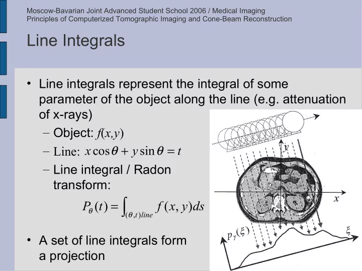
- Line integrals represent the integral of some
parameter of the object along the line (e.g. attenuation
- f x-rays)
– Object: f(x,y) – Line: – Line integral / Radon transform:
- A set of line integrals form
a projection
∫
=
line t
ds y x f t P
) , (
) , ( ) (
θ θ