
SLIDE 1
1
Optical layer protection approaches
Péter Babarczi babarczi@tmit.bme.hu
(János Tapolcai tapolcai@tmit.bme.hu)
2
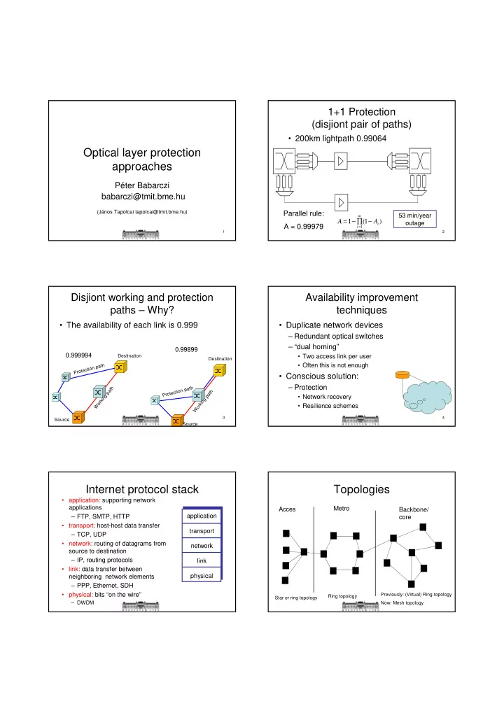
1+1 Protection (disjiont pair of paths)
- 200km lightpath 0.99064
) 1 ( 1
1 i m i
A A − ∏ − =
=
53 min/year
- utage
Parallel rule: A = 0.99979
3
Disjiont working and protection paths – Why?
- The availability of each link is 0.999
Working path Protection path Working path Protection path
0.999994 0.99899
Source Source Destination Destination
4
Availability improvement techniques
- Duplicate network devices
– Redundant optical switches – “dual homing”
- Two access link per user
- Often this is not enough
- Conscious solution:
– Protection
- Network recovery
- Resilience schemes
Internet protocol stack
- application: supporting network
applications – FTP, SMTP, HTTP
- transport: host-host data transfer
– TCP, UDP
- network: routing of datagrams from
source to destination – IP, routing protocols
- link: data transfer between
neighboring network elements – PPP, Ethernet, SDH
- physical: bits “on the wire”
– DWDM
application transport network link physical
Topologies
Acces Metro Backbone/ core
Star or ring topology Ring topology Previously: (Virtual) Ring topology Now: Mesh topology