
SLIDE 1
1 1 1 1
OPNET Implementation of OPNET Implementation of OPNET Implementation of OPNET Implementation of the the the the Megaco/H.248 Protocol: Megaco/H.248 Protocol: Megaco/H.248 Protocol: Megaco/H.248 Protocol: Multi Multi Multi Multi-
- Call and Multi
Call and Multi Call and Multi Call and Multi-
- Connection
Connection Connection Connection Scenarios Scenarios Scenarios Scenarios
Edlic Yiu, Edwood Yiu, and Ljiljana Trajković
Simon Frase r Unive rsity Vancouve r, British Columbia, Canada E-mail: {e nyiu, e yiu, ljilja}@cs.sfu.ca
Abstract Abstract Abstract Abstract In this paper, we describe the OPNET implementation of MEGACO/H.248 signaling protocol. The OPNET model allows for multi-call and multi-connection scenarios, where any number
- f Media Gateways (MGs) can simultaneously connect to the
Media Gateway Controller (MGC). This design is important for simulations of simultaneous voice conversations. In our simulation scenario, multiple MGs can connect to one MGC via a router. We simulated the call-establishment, call-waiting, and call-release scenarios by employing a complete set of MEGACO/H.248 signaling commands. We also simulated voice transmission using packets encoded with the Real-Time Transport Protocol (RTP).
- 1. Introduction
- 1. Introduction
- 1. Introduction
- 1. Introduction
Voice over IP (VoIP) technology is currently finding its place in the telecommunication market. It enables a telecommunication company to cut cost by allowing a single network to transmit both data and voice traffic. In addition, VoIP technology is gaining popularity in both commercial and residential markets because the voice quality resulting from packets transmitted over the IP network is comparable to the voice quality resulting from analog signals sent over the Public Switched Telephone Network (PSTN). The MEGACO/H.248 signaling protocol was introduced by the Internet Engineering Task Force (IETF) and International Telecommunication Union (ITU) to help control and manage the increasing volume of VoIP traffic. With the emergence of VoIP technology, voice traffic is no longer restricted to the circuit-switched network. New IP-based products, such as IP phones and voice cable modems, have been introduced to integrate voice services over the data network. To properly manage and control these voice services, various signaling protocols have been developed. One of these protocols is MEGACO/H.248. It provides the master/slave architecture for controlling VoIP traffic. The MEGACO/H.248 signaling protocol employs a call control
- concept. The call control “intelligence” or the master server
resides in the Media Gateway Controller (MGC), while the Media Gateway (MG) serves as the slave device (dumb terminal). This concept reduces the complexity of the gateway, making it easier and more suitable for mass deployment. In this paper, we describe the implementation and simulation of the MEGACO/H.248 protocol using OPNET. All eight MEGACO commands are implemented: Add, AuditCapabilities, AuditValue, Modify, Move, Notify, ServiceChange, and
- Subtract. The OPNET implementation permits the addition of
multiple MGs. This flexibility is important for realistic simulation scenarios where many voice conversations occur
- simultaneously. Several MGs are connected to a single MGC via
a router. We verified all signaling commands and simulated the MG registration, call-establishment, call-waiting, and call- release scenarios. To verify that voice calls were actually established, we generated voice packets encoded using the RTP protocol. Section 2 describes the history and basic architecture of the MEGACO/H.248 protocol. Sections 3 and 4 describe the design
- f the MEGACO/H.248 protocol, while Section 5 describes its
OPNET implementation. Various call flow simulation scenarios are given in Section 6. Simulation results are presented in Section 7. We conclude with Section 8.
- 2. MEGACO/H.248 Protocol
- 2. MEGACO/H.248 Protocol
- 2. MEGACO/H.248 Protocol
- 2. MEGACO/H.248 Protocol
2.1. History 2.1. History 2.1. History 2.1. History In traditional circuit-switched networks, call setups are performed primarily through the backbone of the telephone
- network. As a result, a proprietary signaling protocol can be
used for establishing and deleting connections. However, a well- defined signaling protocol is required for VoIP because VoIP traffic is routed through the public network infrastructure. Various signaling protocols have been designed to control VoIP
- traffic. Peer-to-peer protocols, such as SIP and H.323, have been
- introduced. However, for large-scale deployments, these
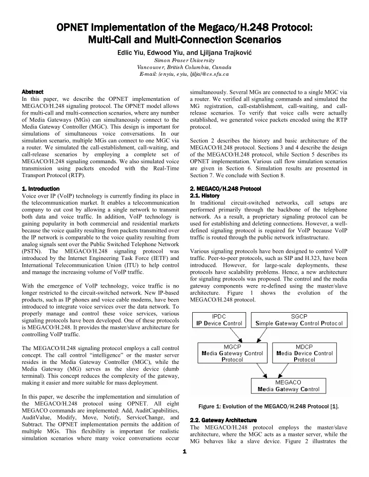
protocols have scalability problems. Hence, a new architecture for signaling protocols was proposed. The control and the media gateway components were re-defined using the master/slave architecture. Figure 1 shows the evolution
- f