SLIDE 1 Octipes Vehiculum
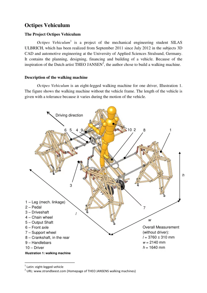
The Project Octipes Vehiculum Octipes Vehiculum1 is a project of the mechanical engineering student SILAS ULBRICH, which has been realized from September 2011 since July 2012 in the subjects 3D CAD and automotive engineering at the University of Applied Sciences Stralsund, Germany. It contains the planning, designing, financing and building of a vehicle. Because of the inspiration of the Dutch artist THEO JANSEN2, the author chose to build a walking machine. Description of the walking machine Octipes Vehiculum is an eight-legged walking machine for one driver, Illustration 1. The figure shows the walking machine without the vehicle frame. The length of the vehicle is given with a tolerance because it varies during the motion of the vehicle.
1 Latin: eight-legged vehicle 2 URL: www.strandbeest.com (Homepage of THEO JANSENS walking machines)
Illustration 1: walking machine
Driving direction l w h 1 – Leg (mech. linkage) 2 – Pedal 3 – Driveshaft 4 – Chain wheel 5 – Output Shaft 6 – Front axle 7 – Support wheel 8 – Crankshaft, in the rear 9 – Handlebars 10 – Driver Overall Measurement (without driver): l = 3760 ± 310 mm
w = 2140 mm
h = 1640 mm 1 2 4 5 6 3 7 8 9 10
SLIDE 2
A simplified kinematic scheme of the vehicle (without the vehicle frame) is shown in Illustration 2. Components 1. Drive System The driver stands upon two pedals (2, Illustration 1 and Illustration 2) and holds onto the handlebars (9). For the force transmission from the driveshaft (3) to the output shaft (5) a single-level chain wheel transmission (4) with a gear ratio of i = 3.5 is used. The drive is carried out by a pedaling movement of the driver with a pedal system which works similar to a cross trainer with a crank rocker mechanism, Illustration 3. The pedals are equipped with an anti-slip-area and Velcro strips to fix the feet.
Illustration 2: Kinematic Scheme of the walking machine, side view
Driving direction 1 2 3 4 5 6 7 1 – Leg 2 – Crank rocker with pedals 3 – Driveshaft 4 – Chain wheel 5 – Output shaft 6 – Front axle 7 – Support wheel 8 – Crank shaft, in the rear 9 – Handlebars 8
Illustration 3: Pedalsystem, isometric view
Driving direction Crank Lever Coupler Frame Support- wheel Pinion Pedal 9
SLIDE 3 The two wheels serve as support wheels because essential components of the walking machine consists of wood (e. g. the legs), which is not designed for carrying the whole load. The foot of the driver is located somewhere on the middle of the coupler (2) and follows a semicircle-shaped path, Illustration 4. Thereby a natural and joint-friendly foot motion of the driver should be achieved. Furthermore the Illustration 4 figures the paths of the pivots A and B. 2. Legs The vehicle moves by making steps forward. For this reason the vehicle possesses mechanical linkages which are commonly called “legs” because of their function, Illustration
- 5. As a template for the legs served the mechanical linkages3 invented by THEO JANSEN.
The trajectories of the input and the output of the mechanical linkage are shown in Illustration 6, as well as the length and height of a step on flat ground.
3 Jansen, T.: Leg System. URL: http://www.strandbeest.com/beests_leg.php, access: 20.07.2012.
Illustration 5: Mechanical Linkage (Leg)
Spring-borne foot Crankshaft Axis
Illustration 6: Trajectories
Driving direction Step height: 250 mm Step length: 650 mm Input Output
Illustration 4: Path of the center of the coupler
2 3 1 1 – Crank 2 – Coupler 3 – Lever A, B – Pivots A0, B0 – Location bearings with pivots Path of the center of the coupler A0 B0 A B Driving direction
SLIDE 4
3. Steering The principle of the steering is unusually concerning the gear and the steering motion in comparison to traditional steering methods in automotive engineering. The steering motion is created by a sliding-swinging movement (a) of the handlebars (1) across the driving direction, Illustration 7. Because of this the steering axis (2) is shift lengthwise (b). The steering axis (2) has a fixed lever (r) with respect to the crankshaft (4, rotation d). Therefore a rotary movement (c) is initiated in the outer parts of the tripartite axis (3). The middle part of the axis (2) is shift parallel because of the geometry. With Illustration 7 it follows a simplified principle sketch of the walking machine with the steering system from the top view (without the drive system).
Illustration 7: Principle sketch of the steering system, top view
r Driving direction 3 3 2 1 1 – Handlebars 2 – Steering axis 3 – Outer part of the axis 4 – Crankshaft 5 – Body 4 a b c c 5 d
SLIDE 5
In Illustration 8 the developed steering system can be seen from the isometric view.
Illustration 8: Steering system, isometric view
1 Handlebars 2 Crankshaft 3 Crank angle 4 Chain wheel 5 Universal joint 6 Length compensation 7 Middle part of the front axle 8 Guide with groove and guide bolt 9 Rotary joint 10 Outer part of the front axle 11 Frame bar and spacer 12 T-piece, axial ensured by cotters Driving direction 11 5 1 4 2 3 10 9 6 7 12 8
SLIDE 6 The distance between the middle part of the front axle (7) and the crankshaft (2) varies during the steering motion and is therefore compensated by the length compensation (6), Illustration 8. However in the outer parts of the axle (10) and crankshaft the distance is constant because of frame bars (11). The pivot of the rotary movement in the outer parts of the front axle (10) lies in the universal joints (5). The handlebar is mounted rotatable with a T- piece (12) on the front axle (7) and is axial ensured by cotters. Because of the rotatability the handlebar to some extent can be swiveled to the desired height respectively distance to the driver. The steering motion is limited because of a bilateral stop, which is realized with a bolt (8) guided in a groove in the front axle. The maximum steering angle amounts ca. 28°. With this the vehicle possesses a theoretical turning cycle of 8.13 m. Application range and technical specifications Table 1 names the application range and the most important technical specifications of the walking machine.
Table 1: Application range and technical specifications of the walking machine
Criterion Value Miscellaneous Intended use Outdoor leisure sports equipment, prototype Number of carried persons 1 Position of the driver Standing Driving energy Muscle strength of the driver Generation of the driving energy Pedalling Number of legs of the walking machine 8 Static equilibrium Yes Target Body height 1.70 m – 1.90 m Body weight 50 kg – 100 kg Fitness of the driver Average sportsmanship Operating environment Operating place Outdoors Subsoil texture No prepared ground necessary, Solid underground,
- Max. unevenness depends on the support-
wheels (Diameter: 260 mm) Terrain slope
Technical specifications Vehicle weight 123 kg Vehicle length 3760 ± 310 mm, Illustration 1 Vehicle width 2140 mm, Illustration 1 Vehicle height 1640 mm (without driver), Illustration 1 Step length 650 mm, Illustration 6 Step height 250 mm, Illustration 6 Turning cycle 8.13 m (calculated) Average velocity 1 – 2 km/h (calculated)
SLIDE 7
Designmodel Using the 3D CAD program SolidWorks, the following virtual Model of the walking machine was created, Illustration 9, 10 and 11. (All others pictures of this presentation where created with SolidWorks too, besides the photographs).
Illustration 11: Model in SolidWorks, dimetric view
Driving direction
Illustration 9: Model in SolidWorks, top view Illustration 10: Model in SolidWorks, front view
SLIDE 8 Functional test After the provisionally completion of building the walking machine and during a test under the full strain a joint broke and further joints crackled. Therefore it turned out that the material of the legs of the walking machine is undersized and the vehicle can`t be used for
- locomotion. The broken part then was repaired.
Thereupon the walking machine was jacked so that the front legs of the walking machine hung free in the air. Hereby a successful functional test could be run. During that test the following picture was taken, Illustration 12.
Illustration 12: Functional test with the jacked walking machine
Furthermore a movie presentation of Octipes Vehiculum was created, which can be found in the internet under the following URL. The movie uses pictures and animations of the 3D CAD program as well as footage of the functional test and further pictures. http://youtu.be/JRnB6YhIcsM, Published on: 28.07.2012, Duration: 3:30 min.
SLIDE 9
Illustration 13 shows a further picture of Octipes Vehiculum after the completion of the building phase.
Illustration 13: Octipes Vehiculum