
SLIDE 1
Nuclei in matter
1
nEDM with Spallation UCN Source of He-II
- Y. Masuda (KEK), April 15, 2016,
Mainz
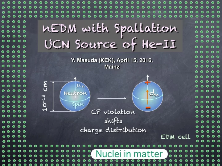
+
- dn
Neutron
10-13 cm
Spin
CP violation shifts charge distribution
μn
EDM cell