nanoscale characterization of oxide dispersion
play

Nanoscale Characterization of Oxide Dispersion Strengthened - PDF document

Transactions of the Korean Nuclear Society Virtual Spring Meeting July 9-10, 2020 Nanoscale Characterization of Oxide Dispersion Strengthened CoCrFeMnNi High-Entropy Alloy by Small Angle Neutron Scattering SeungHyeok Chung, Ho Jin Ryu


  1. Transactions of the Korean Nuclear Society Virtual Spring Meeting July 9-10, 2020 Nanoscale Characterization of Oxide Dispersion Strengthened CoCrFeMnNi High-Entropy Alloy by Small Angle Neutron Scattering SeungHyeok Chung, Ho Jin Ryu  Nuclear and Quantum Engineering Department, Korea Advanced Institute of Science and Technology, 291 Daehakro, Yuseong, Daejeon, 34141, Republic of Korea * Corresponding author: hojinryu@kaist.ac.kr 1. Introduction employed. Mechanical alloying was conducted for 24 
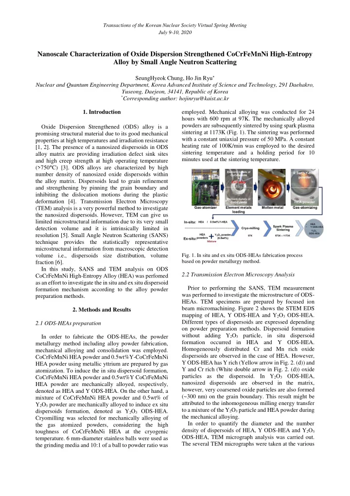
hours with 600 rpm at 97K. The mechanically alloyed powders are subsequently sintered by using spark plasma Oxide Dispersion Strengthened (ODS) alloy is a sintering at 1173K (Fig. 1). The sintering was performed promising structural material due to its good mechanical with a constant uniaxial pressure of 50 MPa. A constant properties at high temperatures and irradiation resistance heating rate of 100K/min was employed to the desired [1, 2]. The presence of a nanosized dispersoids in ODS sintering temperature and a holding period for 10 alloy matrix are providing irradiation defect sink sites minutes used at the sintering temperature. and high creep strength at high operating temperature (>750 ° C) [3]. ODS alloys are characterized by high number density of nanosized oxide dispersoids within the alloy matrix. Dispersoids lead to grain refinement and strengthening by pinning the grain boundary and inhibiting the dislocation motions during the plastic deformation [4]. Transmission Electron Microscopy (TEM) analysis is a very powerful method to investigate the nanosized dispersoids. However, TEM can give us limited microstructural information due to its very small detection volume and it is intrinsically limited in resolution [5]. Small Angle Neutron Scattering (SANS) technique provides the statistically representative microstructural information from macroscopic detection volume i.e., dispersoids size distribution, volume Fig. 1. In situ and ex situ ODS-HEAs fabrication process based on powder metallurgy method. fraction [6]. In this study, SANS and TEM analysis on ODS 2.2 Transmission Electron Microscopy Analysis CoCrFeMnNi High-Entropy Alloy (HEA) was perfomed as an effort to investigate the in situ and ex situ dispersoid Prior to performing the SANS, TEM measurement formation mechanism according to the alloy powder was performed to investigate the microstructure of ODS- preparation methods. HEAs. TEM specimens are prepared by focused ion beam micromachining. Figure 2 shows the STEM EDS 2. Methods and Results mapping of HEA, Y ODS-HEA and Y 2 O 3 ODS-HEA. Different types of dispersoids are expressed depending 2.1 ODS-HEAs preparation on powder preparation methods. Dispersoid formation without adding Y 2 O 3 particle, in situ dispersoid In order to fabricate the ODS-HEAs, the powder formation occurred in HEA and Y ODS-HEA. metallurgy method including alloy powder fabrication, Homogeneously distributed Cr and Mn rich oxide mechanical alloying and consolidation was employed. dispersoids are observed in the case of HEA. However, CoCrFeMnNi HEA powder and 0.5wt%Y-CoCrFeMnNi Y ODS-HEA has Y rich (Yellow arrow in Fig. 2. (d)) and HEA powder using metallic yttrium are prepared by gas Y and Cr rich (White double arrow in Fig. 2. (d)) oxide atomization. To induce the in situ dispersoid formation, particles as the dispersoid. In Y 2 O 3 ODS-HEA, CoCrFeMnNi HEA powder and 0.5wt%Y CoCrFeMnNi nanosized dispersoids are observed in the matrix, HEA powder are mechanically alloyed, respectively, however, very coarsened oxide particles are also formed denoted as HEA and Y ODS-HEA. On the other hand, a (~300 nm) on the grain boundary. This result might be mixture of CoCrFeMnNi HEA powder and 0.5wt% of attributed to the inhomogeneous milling energy transfer Y 2 O 3 powder are mechanically alloyed to induce ex situ to a mixture of the Y 2 O 3 particle and HEA powder during dispersoids formation, denoted as Y 2 O 3 ODS-HEA. the mechanical alloying. Cryomilling was selected for mechanically alloying of In order to quantify the diameter and the number the gas atomized powders, considering the high density of dispersoids of HEA, Y ODS-HEA and Y 2 O 3 toughness of CoCrFeMnNi HEA at the cryogenic ODS-HEA, TEM micrograph analysis was carried out. temperature. 6 mm-diameter stainless balls were used as The several TEM micrographs were taken at the various the grinding media and 10:1 of a ball to powder ratio was

  2. Transactions of the Korean Nuclear Society Virtual Spring Meeting July 9-10, 2020 magnifications and the dispersoids are counted to obtain the statistically proper dispersoids information as shown A SANS measurement performed using EQ-SANS in figure 3. Nano dispersoids, formed by in situ instrument at ORNL. Figure 4 shows SANS intensities dispersoid formation, smaller than 25 nm in diameter are from the HEA, Y ODS-HEA and Y 2 O 3 ODS-HEA observed. Meanwhile, coarsening of dispersoids is sintered at 1173K. The SANS profiles from ODS-HEAs observed in Y 2 O 3 ODS-HEA, which was fabricated by have different forms due to different dispersoid size the ex situ dispersoid formation method. distribution and dispersoid types. The SANS profiles are fitted by IRENA software package, Unified fit, developed by Argonne National Laboratory [7]. The unified fit is an appropriate tool to deal with data for which a specific scattering model does not exist [7, 8]. The intensity is given by: 𝑄 𝑟𝑆𝑕 erf( √6 ) 𝑟 2 𝑆 𝑕 2 𝑟 2 𝑆 𝑕 2 𝐽(𝑟) = 𝐻𝑓𝑦𝑞 (− 3 ) + exp (− 3 ) 𝐶 { } (1) 1 where 𝐻 is the Guinier prefactor and 𝐶 is the Porod constant. 𝑟 is defined as 4 π sin θ / λ , θ is the scattering angle and λ is the wavelength of the neutron. Figure 5 shows the dispersoid size distribution obtained from the data of ODS-HEAs. A bimodal size distribution and much higher density of the smaller dispersoid size distribution are confirmed at entire ODS- HEAs. The smallest dispersoid size distributions are detected in the Y ODS-HEA, followed by HEA and Y 2 O 3 ODS-HEA, which has good agreement with TEM results. 100 10 HEA Y ODS-HEA 1 Y 2 O 3 ODS-HEA 0.1 I(q) 0.01 0.001 1E-4 1E-5 1E-6 0.01 0.1 1 Fig. 2. STEM images of (a), (b) HEA, (c), (d) Y ODS- q ( Å ) HEA and (e), (f) Y 2 O 3 ODS-HEA. Fig. 4. SANS intensities of HEA, Y ODS-HEA and Y 2 O 3 ODS-HEA sintered at 1173K. 1E23 200 Dispersoid Number Density (m -3 ) Dispersoid Diameter (nm) 1E22 150 1E21 100 1E20 50 1E19 0 HEA Y Y2O3 ODS-HEA ODS-HEA Fig. 3. Dispersoid number density and diameter of ODS- HEAs estimated by TEM micrographs analysis 2.3 SANS measurement

  3. Transactions of the Korean Nuclear Society Virtual Spring Meeting July 9-10, 2020 Fig. 5. Comparison of dispersoid sizes distribution 3. Conclusions ODS HEAs are successfully prepared by the powder metallurgy method including gas atomization, cryomilling and spark plasma sintering. The influence of powder preparation on microstructure of ODS-HEAs was investigated. SANS and TEM analysis identified that in situ dispersoid formation can refine the dispersoid size with high number density. However, ex situ dispersoid formation causes coarsening of dispersoids. ACKNOWLEDGEMENT The SANS measurements were performed at the Spallation Neutron Source (SNS) Extended Q-Range Small Angle Neutron Scattering (EQ-SANS), Oak Ridge National Laboratory (ORNL). The present work has been supported by Agency for Defense Development (ADD) of Republic of Korea under the contract 1415156504. REFERENCES F. Siska et al. , “Strengthening mechanisms of [1] different oxide particles in 9Cr ODS steel at high temperatures,” Mater. Sci. Eng. A , vol. 732, no. June, pp. 112 – 119, 2018. S. J. Zinkle and G. S. Was, “Materials challenges in [2] nuclear energy,” Acta Mater. , vol. 61, no. 3, pp. 735 – 758, 2013. [3] E. Gil, N. Ordás, C. García-Rosales, and I. Iturriza, “Microstructural characterization of ODS ferritic steels at different processing stages,” Fusion Eng. Des. , vol. 98 – 99, pp. 1973 – 1977, 2015. [4] M. Nagini, R. Vijay, K. V. Rajulapati, A. V. Reddy, and G. Sundararajan, “Microstructure– mechanical property correlation in oxide dispersion strengthened 18Cr ferritic steel,” Mater. Sci. Eng. A , vol. 708, no. June, pp. 451 – 459, 2017. [5] R. Coppola, M. Klimiankou, R. Lindau, R. P. May, and M. Valli, “SANS and TEM study of y2O3 particle distributions in oxide-dispersion strengthened EUROFER martensitic steel for fusion reactors,” Phys. B Condens. Matter , vol. 350, no. 1-3 SUPPL. 1, pp. 545 – 548, 2004. [6] International Atomic Energy Agency. and IAEA, “Small angle neutron scattering,” IAEA Rep. 2000- 2003 , no. March, p. 113, 2006. J. Ilavsky and P. R. Jemian, “Irena: Tool suite for [7] modeling and analysis of small- angle scattering,” J. Appl. Crystallogr. , vol. 42, no. 2, pp. 347 – 353, 2009. [8] G. Beaucage, H. K. Kammler, and S. E. Pratsinis, “Particle size distributions from small -angle scattering using global scattering functions,” J. Appl. Crystallogr. , vol. 37, no. 4, pp. 523 – 535, 2004. [9] G. Beaucage, S. Rane, S. Sukumaran, M. M. Satkowski, L. A. Schechtman, and Y. Doi, “Persistence length of isotactic poly(hydroxy butyrate),” Macromolecules , vol. 30, no. 14, pp. 4158 – 4162, 1997.

Download Presentation
Download Policy: The content available on the website is offered to you 'AS IS' for your personal information and use only. It cannot be commercialized, licensed, or distributed on other websites without prior consent from the author. To download a presentation, simply click this link. If you encounter any difficulties during the download process, it's possible that the publisher has removed the file from their server.

Recommend


More recommend