
SLIDE 1
Nano-wire Photoelectrochemical cell
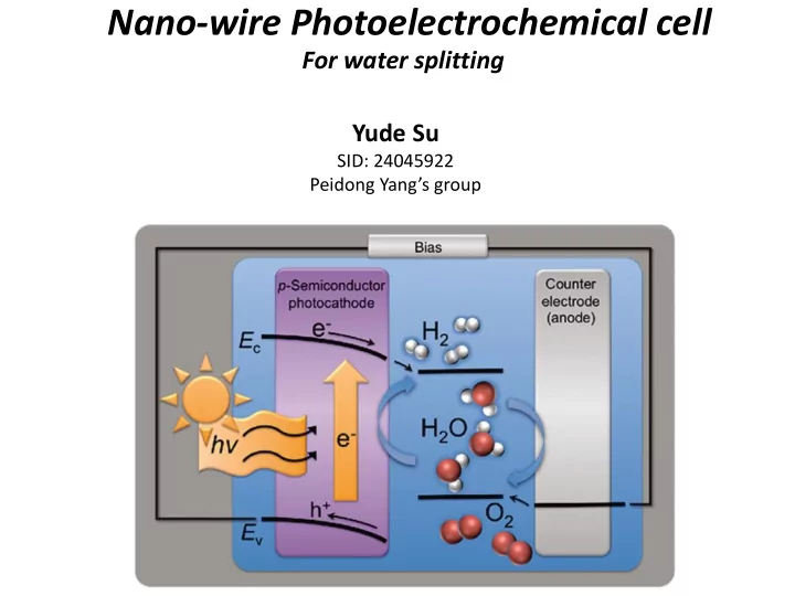
For water splitting Yude Su
SID: 24045922 Peidong Yang’s group
Nano-wire Photoelectrochemical cell For water splitting Yude Su - - PowerPoint PPT Presentation
Nano-wire Photoelectrochemical cell For water splitting Yude Su SID: 24045922 Peidong Yangs group Outline 1. Motivation of PEC 2. Mechanism of PEC 3. Some examples 4. Future direction Motivation Renewable Energy replace Fossil Fuel
For water splitting Yude Su
SID: 24045922 Peidong Yang’s group
264 GW (2008) 70 GWe (2011) Car running on Biomass (WW II) Car running on Solar (2012)
Photochemical cell Photovoltaic cell
H2O Photocatalyst H2 and O2
η1>20%
Electricity
η2>80% η3<<1%
PV Device + Electrochemical Reaction
6
qM qS q ECB EVB EFM EFS before contact qM qS q ECB EVB EFM EFS after contact qVi qVi qB W
A i
qN V W 2
+ + + +
Schottky contact: M/pS with M < S
7
qM qS q ECB EVB EFM EFS before contact qM qS q ECB EVB EFM EFS after contact + + + +
Ohmic contact: M/nS with M > S
8
light emission from semiconductors
+ + + + + + CB VB excitation
+ + + + + + + + +
excitation off
+ + + + + + + + + + + +
+
after time
Butler-Volmer Equation Current-Overpotential link
/ (1 ) / 1
[ ] ( 0) ( 0)
nF RT nF RT
J J e e J k FC x C x
η: over-potential, defined by E-Eeq J0: exchange current density K0: the standard rate constant, defined by the activation energy when kO=kR α: the transfer coefficient
Cathode Counter Electrode O R R O Mass transport E1 E2 EEq EC
Equivalent Circuit for a PEC cathode
V E2 Butler-Volmer Term Behave as a Series Resistance in the PEC Equivalent Circuit!
( )/ ( )/2 / ( 1) /
( 1) ( 1) ( ) / [ ]
q V KT q V KT s RG sh L nF RT nF RT
I I e I e V R I I e e
0.1 0.2 0.3 0.4 0.5
5 Voltage(V vs Solution) Current(mA) Roughness factor=100 Red: Methyl Viologen Purple: H2 evolution 100%Pt coating Blue: H2 evolution 50%Pt coating Green: H2 evolution 10%Pt coating Cyan-blue: H2 evolution 1%Pt coating Yellow: H2 evolution 0.1%Pt coating Brown: H2 evolution 0.01%Pt coating
VOC: Open circuit voltage ISC: Short circuit current FF: Fill factor=
/ *
Max OC SC
P V I
/
Max input
P P
Why to choose Nanowire as the PEC electrode?
(Surface chemistry)
(Optical absorption)
(Charge transport)
Resultant improvement of photoelectrode
Nanowire for PEC cathode
Si
GaP
Nanowire for PEC anode
TiO2
ZnO
Z-scheme
Energy Diagram Current matching