
SLIDE 1
Mu2e Calorimeter
May 10, 2016
- I. Sarra / Mu2e Grounding & Shielding Review
1
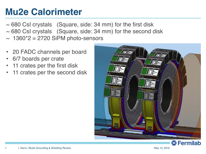
~ 680 CsI crystals (Square, side: 34 mm) for the first disk ~ 680 CsI crystals (Square, side: 34 mm) for the second disk ~ 1360*2 = 2720 SiPM photo-sensors
- 20 FADC channels per board
- 6/7 boards per crate
- 11 crates per the first disk
- 11 crates per the second disk